Drilling machine sound wave power head eccentric vibration generating device

A vibration generation and power head technology, applied in the field of power heads, can solve the problems of poor vibration stability and low vibration transmission efficiency, and achieve the effects of small vibration inertia, high vibration transmission efficiency, and ensuring installation position accuracy.

Pending Publication Date: 2020-07-24
溧阳市东南机械有限公司
View PDF5 Cites 0 Cited by
  • Summary
  • Abstract
  • Description
  • Claims
  • Application Information

AI Technical Summary

Problems solved by technology

[0006] The purpose of the present invention is to overcome the deficiencies such as poor vibration stability and low vibration transmission efficiency of the main shaft vibration generator in the existing eccentric vibration type acoustic wave power head, and provide a kind of eccentric vibration generator for the acoustic wave power head of a drilling rig, which adopts the technology of the present invention Scheme, the main shaft of the sonic power head and the main shaft hydraulic motor are connected by a spline structure, and the main shaft hydraulic motor drives the main shaft to rotate. The vibration mechanism is symmetrically arranged in the headstock, and two sets of eccentric vibration mechanisms are respectively placed on the left and right sides of the main shaft. The two sets of eccentric vibration mechanisms in the headstock box generate high-frequency vibration, and the non-axis vibration of the main shaft is small, so that the main shaft generates The excitation is more stable, the vibration transmission efficiency is higher, and the structure of the sonic power head is more reasonable and compact, which is easy to assemble and manufacture, and has a long service life

Method used


Image

  • Drilling machine sound wave power head eccentric vibration generating device
  • Drilling machine sound wave power head eccentric vibration generating device
  • Drilling machine sound wave power head eccentric vibration generating device

Examples


Embodiment

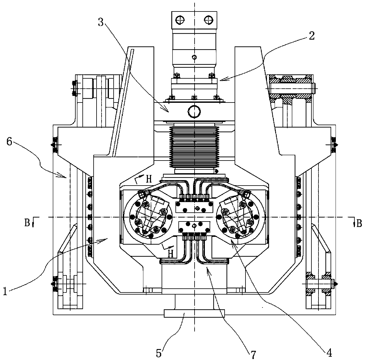
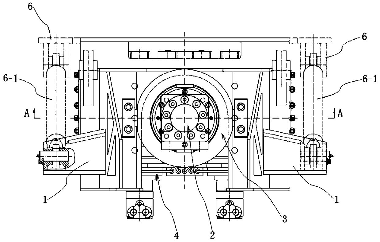
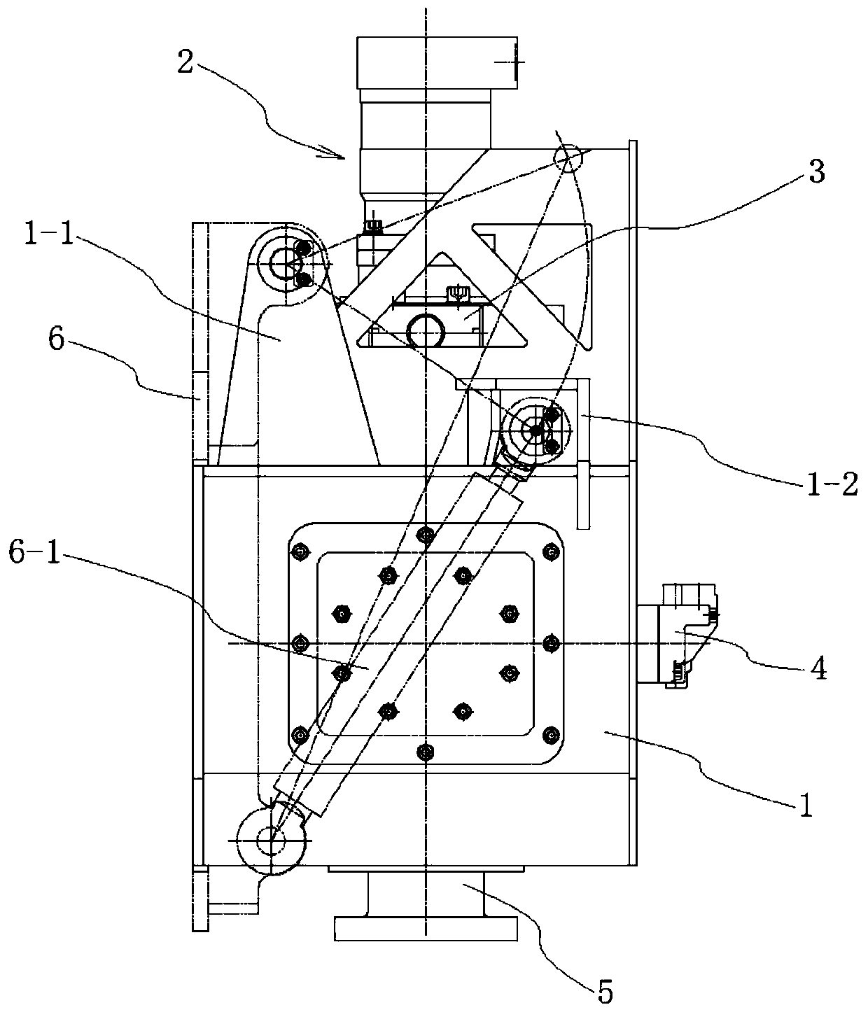
[0055] combine Figure 1 to Figure 5 As shown, an eccentric vibration generating device of a drilling rig sonic power head in this embodiment includes a main frame 1, a main shaft rotating mechanism 2 and a main shaft vibrating mechanism 4, and the main frame 1 is used as a supporting part of the whole sonic power head for installing the main shaft rotating Mechanism 2 and spindle vibration mechanism 4, wherein: spindle rotation mechanism 2 includes spindle hydraulic motor 2-1 and spindle 2-7, spindle hydraulic motor 2-1 is installed on the upper part of main frame 1, and the output of spindle hydraulic motor 2-1 The shaft and the main shaft 2-7 are connected by a spline structure transmission to drive the main shaft 2-7 to rotate and allow the main shaft 2-7 to move up and down in the axial direction; the main shaft vibration mechanism 4 includes a main shaft box 4-1 and a vibration isolator 4 -2 and two sets of symmetrically arranged eccentric vibration mechanisms, the main ...


PUM


Abstract

The invention discloses a drilling machine sound wave power head eccentric vibration generating device, and belongs to the field of audio frequency drilling machines. The eccentric vibration generating device comprises a main frame, a main shaft rotating mechanism and main shaft vibration mechanisms, a main shaft of a sound wave power head is in transmission connection with a main shaft hydraulicmotor through a spline structure, the main shaft is rotationally installed in a main shaft box, the main shaft box is installed in the main frame in a suspended mode through a vibration isolator, twoeccentric vibration mechanisms are symmetrically arranged in the main shaft box and are arranged on the left side and the right side of the main shaft correspondingly, high-frequency vibration is generated through the two eccentric vibration mechanisms in the main shaft box, rotating motion and vibration of the main shaft do not affect each other, vibration inertia is small, non-main shaft axial vibration is small, excitation generated by the main shaft is more stable, and vibration transmission efficiency is higher; and the sound wave power head is more reasonable and compact in structure, the installation position precision of two eccentric vibrator shafts is easily guaranteed, assembling and manufacturing are convenient, and the service life of the sound wave power head is prolonged.

Description

technical field [0001] The invention relates to a power head of a drilling rig, and more specifically relates to an eccentric vibration generating device of a sonic wave power head of a drilling rig. Background technique [0002] In the construction process of oil field, mineral exploration, geotechnical survey and soil sampling, etc., drilling rig is a commonly used mechanical equipment for soil and rock drilling. The sonic power head for drilling rigs can generate up and down vibrations to act on the drilling tools during the drilling process. Compared with traditional rotary drilling rigs, it has the advantages of fast drilling speed, high work efficiency, high fidelity of rock and soil samples, and excellent construction efficiency. It has the advantages of good safety and less environmental pollution. When the sonic power head is drilling, the resonance energy is transmitted to the working face of the drill bit through the drill string, and at the same time, the low-sp...

Claims


Application Information

Patent Timeline
Patent Type & Authority Applications(China)
IPC IPC(8): E21B7/24E21B3/02E21B7/10E21B44/00E21B47/00
CPCE21B3/02E21B7/10E21B7/24E21B44/00E21B47/00
Inventor 潘云雨高翔潘俊
Owner 溧阳市东南机械有限公司
Why Eureka
Try Eureka