Electromagnetic direct-drive linear hydraulic pump based on dissymmetric-flow-pass heat dissipation

An asymmetric, hydraulic pump technology, which is applied to parts, pumps, and pump components of pumping devices for elastic fluids, can solve problems such as internal heat dissipation difficulties, electromagnetic direct-drive plunger pump heating, etc., and achieve compact structure, Solve severe fever and enhance the effect of air gap magnetic field strength

Pending Publication Date: 2020-07-24
SHANDONG UNIV OF TECH
View PDF0 Cites 2 Cited by
  • Summary
  • Abstract
  • Description
  • Claims
  • Application Information

AI Technical Summary

Problems solved by technology

[0005] The purpose of designing an electric coupling sleeve type shifting mechanism is to use the linear actuator mover to directly drive the hydraulic cylinder piston to reciprocate, and the pump liquid chamber to complete the pumping of the liquid under the flow distribution of the one-way valve group, and at the same time in the pump air chamber The pump sucks air to implement forced air cooling and heat dissipation inside the linear actuator, which solves the problem of serious heat generation of the electromagnetic direct drive plunger pump, especially the difficulty of internal heat dissipation, without adding additional devices and without affecting the compactness of the structure.

Method used


Image

  • Electromagnetic direct-drive linear hydraulic pump based on dissymmetric-flow-pass heat dissipation
  • Electromagnetic direct-drive linear hydraulic pump based on dissymmetric-flow-pass heat dissipation

Examples


Embodiment Construction

[0018] The present invention will be further described in detail below in conjunction with the accompanying drawings and specific embodiments.

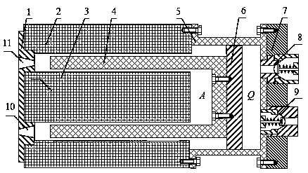
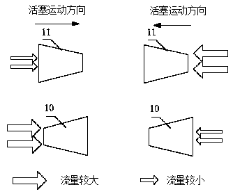
[0019] like Figures 1 to 2 As shown, an electromagnetic direct-drive linear hydraulic pump based on asymmetric flow channel heat dissipation includes an end cover (1), an outer stator of a linear actuator (2), an inner stator of a linear actuator (3), and a mover of a linear actuator ( 4), hydraulic cylinder (5), piston (6), valve body (7), liquid outlet valve (8), liquid inlet valve (9), inlet flow channel (10) and exhaust flow channel (11); Its features include that the outer stator (2) and the inner stator (3) of the linear actuator are coaxially fixed through the end cover (1), and the outer stator (2) and the valve block (7) of the linear actuator are adopted through the cylinder block (5) of the linear actuator. The screws are coaxially fixed and the axial end faces are parallel to each other. The valve body (7) is equipped wi...


PUM


Abstract

The invention relates to an electromagnetic direct-drive linear hydraulic pump based on dissymmetric-flow-pass heat dissipation. The pump comprises a linear actuator rotor, linear actuator stators, anend cover, a hydraulic cylinder block, a piston, an air inlet flow pass, an exhaust flow pass, a valve body and a one-way valve. The pump is characterized in that the linear actuator rotor is integrated with the piston of the hydraulic piston to serve as a rotor, and an inner chamber of the hydraulic pump is divided into a pump liquid chamber Q and a pump air chamber A; the linear actuator outerstator and the linear actuator inner stator are axially fixed through the end cover, an air gap is formed between the linear actuator outer stator and the linear actuator inner stator, and the linearactuator outer stator is fixedly connected with the hydraulic cylinder block, fixedly connected with the valve body, to serve as a stator; the pump air chamber A communicates with the environment through the air gap, the air inlet flow pass and the exhaust flow pass respectively, and the axial section of each flow pass is trapezoid; and the linear actuator rotor directly drives the piston to moveback and forth, and is used in cooperation with the air inlet flow pass and the exhaust flow pass to carry out pump suction of air in the pump air chamber to carry out air cooling heat dissipation onthe interior of the linear actuator. With the electromagnetic direct-drive linear hydraulic pump based on dissymmetric-flow-pass heat dissipation, the problems that an electromagnetic direct-drive linear hydraulic pump emits much heat, and particularly, the heat inside is difficult to emit are solved.

Description

technical field [0001] The invention relates to the technical field of linear hydraulic pumps, in particular to an electromagnetic direct-drive linear hydraulic pump. Background technique [0002] The plunger pump has the advantages of high rated pressure, compact structure, large driving power, long service life and variable flow, and is widely used in construction machinery, aerospace and other fields. Among them, the swash plate type plunger pump has high efficiency, good pressure resistance performance, and can realize various variable functions, and is the mainstream plunger pump in the current market. However, there are many friction pairs and the lubrication conditions are complicated, which also limits the further improvement of its performance. [0003] With the development of linear direct drive technology, the use of linear actuators to directly drive the plunger pump piston, thereby canceling the "swash plate" and other rotary-to-linear motion conversion mechani...

Claims


Application Information

Patent Timeline
Patent Type & Authority Applications(China)
IPC IPC(8): F04B17/04F04B53/08F04B53/10F04B53/14F04B49/22H02K33/18
CPCF04B17/04F04B49/22F04B53/08F04B53/10F04B53/14H02K33/18
Inventor 陆佳瑜谭草葛文庆李波鲁应涛孙宾宾
Owner SHANDONG UNIV OF TECH
Why Eureka
Try Eureka