
Air floating support system

A support system and air flotation technology, applied in the field of bearing structure, can solve the problems of small mass, poor capacity and small bearing capacity of suspended objects, and achieve the effect of increasing the suspension force, wide application range and simple structure

Pending Publication Date: 2020-07-24
DALIAN NATIONALITIES UNIVERSITY
View PDF0 Cites 4 Cited by
  • Summary
  • Abstract
  • Description
  • Claims
  • Application Information

AI Technical Summary

Problems solved by technology

Ultrasonic standing wave has poor suspending ability and small carrying capacity, requiring the suspended objects to be of small mass

Method used


Image

  • Air floating support system
  • Air floating support system
  • Air floating support system

Examples


Embodiment Construction

[0023] It can be seen from the accompanying drawings that the present invention uses piezoelectric ceramic materials to make radial and axial near-field ultrasonic levitation structures, and realizes the radial and axial free movement of the rotor through the mixed suspension of air flotation and near-field ultrasonic levitation. Contact stabilizer.

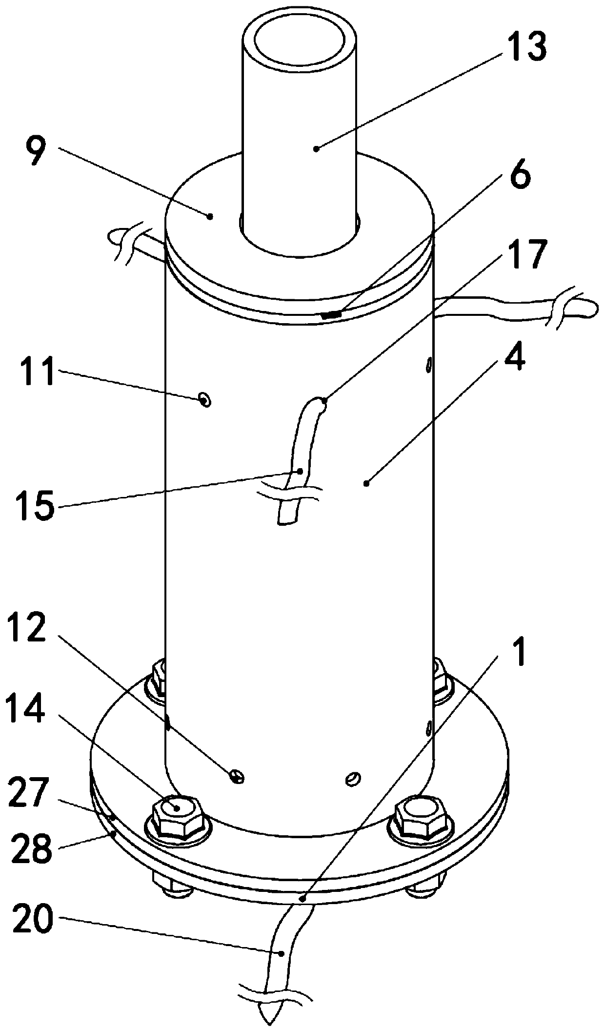
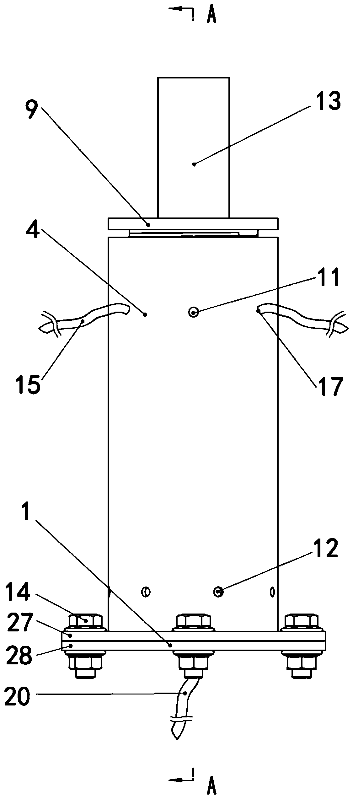
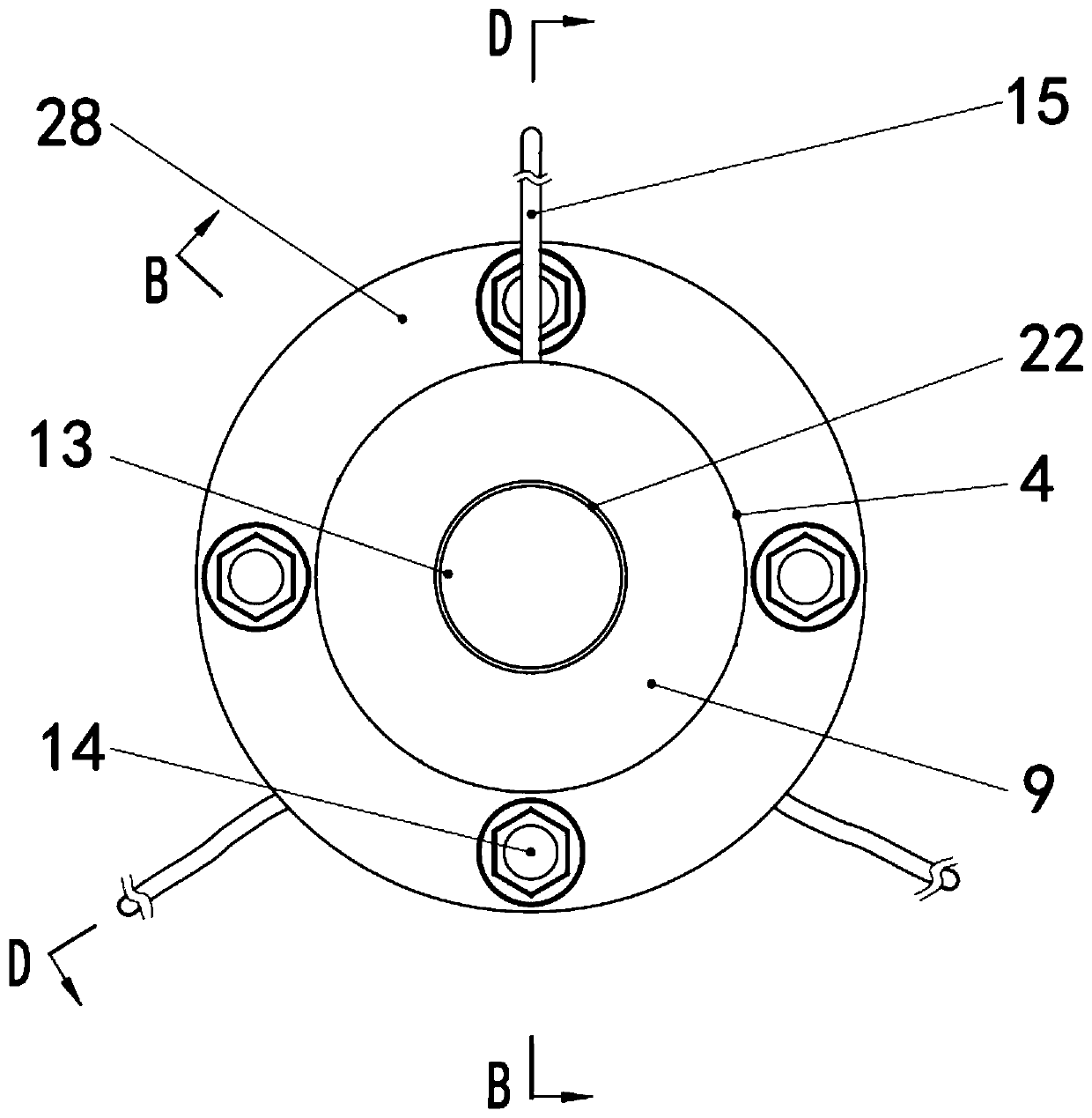
[0024] An air bearing system, characterized in that: a boss 24 with a shaft hole 5 is arranged above the inside of the shell 4, the inside of the shell 4 is divided into two parts by the boss 24, and the upper side of the boss 24 is an upper cavity 16, The lower side is the lower cavity 29 . The lower end of the shell 4 is provided with a flange 27, and a support base 1 with a flange 28 is provided below the flange 27. The flange 27 and the flange 28 are provided with through holes and are fixedly connected together by bolts 14. The upper cavity The inner wall of 16 is provided with the circumferential positioning groove 6 of th...


PUM


Abstract

The invention discloses an air floating support system. A piezoelectric ceramic ring is arranged above a support base, and a conical stator is arranged above the piezoelectric ceramic ring. A shaft rotor is arranged at the upper end of the conical stator, and an orifice is formed in the middle of the conical stator. A shell is arranged on the support base in a sleeved mode, a shaft hole and a positioning groove are formed in the shell, and a prism sleeve affixed with rectangular piezoelectric patches is placed in the positioning groove. A fastening end cover is arranged at the top of the shell, and the shaft rotor passes through the shaft hole, the prism sleeve and the fastening end cover. A high-pressure air pipe passes through the base and the shell to introduce high pressure gas respectively to the clearance of the conical stator and the radial clearance of the prism sleeve to form high pressure gas films. According to the inverse piezoelectric effect, the wall of the prism sleeve and the conical stator are driven by a piezoelectric material to vibrate with high frequency to produce ultrasonic excitation which acts on the high pressure gas films in the clearances, and a mixed suspension force is produced. The axial and radial controllable suspension of the rotor is realized by changing air pressure and voltage parameters. The air floating support system has a simple drivingstructure and no wear and tear, is intelligently controllable, and is suitable for some high-precision and pollution-free fields.

Description

technical field [0001] The invention relates to a bearing structure. Background technique [0002] Air bearings are also called gas bearings. Plain bearings with air as lubricant. During normal operation, the shaft and the bearing surface are completely separated by the air film, and the shaft and external force load are supported by the pressure change in the air film. Because air is less viscous than oil, high temperature resistant, and non-polluting, air bearings can be used in high-speed machines, instruments, and radioactive devices. However, this support system has small load-bearing capacity, low rigidity, poor stability, and is prone to air hammer phenomenon. etc., strict requirements on working conditions. [0003] The phenomenon of acoustic levitation was first discovered in 1866. This phenomenon is a nonlinear effect formed under the action of high-intensity sound waves. Ultrasonic levitation is not limited by materials. According to different levitation work...

Claims


Application Information

Patent Timeline
Patent Type & Authority Applications(China)
IPC IPC(8): F16C32/06F16C32/04
CPCF16C32/0622F16C32/0402F16C32/0404F16C32/067F16C32/0696
Inventor 李东明贾颖胡红英高天一吕帅
Owner DALIAN NATIONALITIES UNIVERSITY
Learn More