
Passive night vision intelligent mine detection system and intelligent mine detection method

A passive, night vision technology, applied in the detection of scattered landmines, night vision intelligent mine detection systems and mine detection fields, it can solve the problems of low detection accuracy, slow detection speed, and poor imaging quality.

Pending Publication Date: 2020-07-24
SHANGHAI UNIV +1
View PDF6 Cites 4 Cited by
  • Summary
  • Abstract
  • Description
  • Claims
  • Application Information

AI Technical Summary

Problems solved by technology

At present, there are still problems such as poor imaging quality, low detection accuracy and slow detection speed when detecting landmines thrown at night. The present invention is aimed at this key problem.

Method used


Image

  • Passive night vision intelligent mine detection system and intelligent mine detection method
  • Passive night vision intelligent mine detection system and intelligent mine detection method
  • Passive night vision intelligent mine detection system and intelligent mine detection method

Examples


Embodiment 1

[0058] In this example, see figure 1 , a passive night vision intelligent mine detection system, comprising a low-light camera 101, a fixed-focus lens 102, a Cameralink data transmission line 103, an FPGA development board 104, a display screen 105, a support frame 106, a lead storage battery 107, and an instrument loading vehicle 108; The fixed-focus lens 102 is connected to the low-light camera 101 through an F bayonet, the low-light camera 101 is placed on the support frame 106, and the FPGA development board 103 is connected to the micro-light through the Cameralink data transmission line 103. Optical camera 101, described FPGA development board 103 is connected with described display screen 105 by data line, and described lead storage battery 107 is by power supply for described micro-light camera 101, described FPGA development board 104 and described display screen 105, described Support frame 106, described FPGA development board 104, described display screen 105, desc...

Embodiment 2

[0102] This embodiment is basically the same as Embodiment 1, especially in that:

[0103] In this embodiment, a passive night vision intelligent mine detection method adopts the passive night vision intelligent mine detection system of this embodiment. Set the area to be detected as an obstacle-free area or a low-alert area, and then mark it on the map; and manually shut down the passive night vision intelligent mine detection system, or increase the wireless or wired signal module to control the passive night vision intelligent detection system. The mine system is shut down, thereby completing the detection task of identifying and ranging the scattered landmines 109 in the area to be detected.


PUM


Abstract

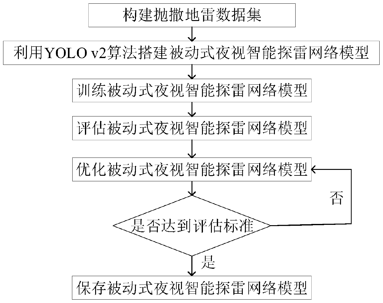
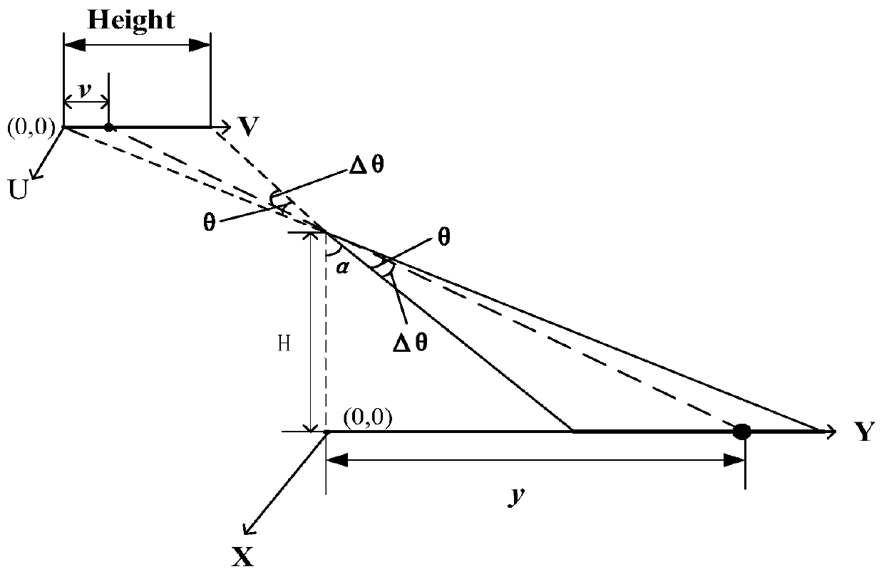
The invention discloses a passive night vision intelligent mine detection system and an intelligent mine detection method. According to the system, a prime lens is connected with a low-light-level camera through an F bayonet; the low-light-level camera is placed on a support frame; an FPGA development board is connected with the low-light-level camera through a data transmission line and is connected with a display screen through a data line; a lead storage battery is sequentially connected with the low-light-level camera, the FPGA development board and the display screen through data lines; and all the parts are placed on an instrument loading vehicle. The method comprises the following steps of: constructing a passive night vision intelligent mine detection network model by using a YOLOv2 algorithm, constructing a data set of scattered landmines, training, evaluating and optimizing the passive night vision intelligent mine detection network, and embedding the trained passive night vision intelligent mine detection network model into the FPGA development board; constructing a passive night vision intelligent mine detection and distance measurement model by applying a geometrical optics imaging principle, and embedding the passive night vision intelligent mine detection and distance measurement model into the FPGA development board. According to the invention, intelligent and rapid detection of thrown landmines at night is realized.

Description

technical field [0001] The invention relates to a mine detection system and method, in particular to a night-vision intelligent mine detection system and mine detection method, which are applied in the technical field of landmine detection technology. Background technique [0002] Modern warfare attaches great importance to rapid maneuvering, and at the same time requires an all-weather observation and surveillance mechanism. The rapid detection of landmines at night is one of the important factors to ensure the rapid maneuvering of night wars. At present, there are two main night detection technologies for scattered landmines: imaging technology detection and non-imaging technology detection. Non-imaging technology, such as pulse radar, obtains the radiation signal of landmines through active and passive working methods, and uses signal processing technology and pattern recognition technology to detect target signals. It is difficult to detect landmines scattered at night...

Claims


Application Information

Patent Timeline
IPC IPC(8): G06T7/73G06K9/00G06N3/04G06N3/08G06K9/62
CPCG06T7/75G06N3/082G06V20/20G06N3/045G06F18/214
Inventor 王驰于明坤李思远李富迪孙建美朱俊栾信群方东李金辉
Owner SHANGHAI UNIV
Learn More