Polyurethane foaming equipment capable of adding powder components for multi-channel pouring

A foaming equipment, multi-flow channel technology, applied in the directions of roads, tracks, ballast layers, etc., can solve the problems of low foaming operation efficiency and achieve the effect of improving operation efficiency

Pending Publication Date: 2020-07-28
成都东日瑞姆机械有限公司
View PDF0 Cites 1 Cited by
  • Summary
  • Abstract
  • Description
  • Claims
  • Application Information

AI Technical Summary

Problems solved by technology

[0005] The purpose of the present invention is to provide polyurethane foaming equipment that can add powder components and cast in multiple channels, so as to solve the problem of low efficiency of on-site pouring and foaming of polyure...

Method used


Image

  • Polyurethane foaming equipment capable of adding powder components for multi-channel pouring
  • Polyurethane foaming equipment capable of adding powder components for multi-channel pouring
  • Polyurethane foaming equipment capable of adding powder components for multi-channel pouring

Examples


Embodiment 1

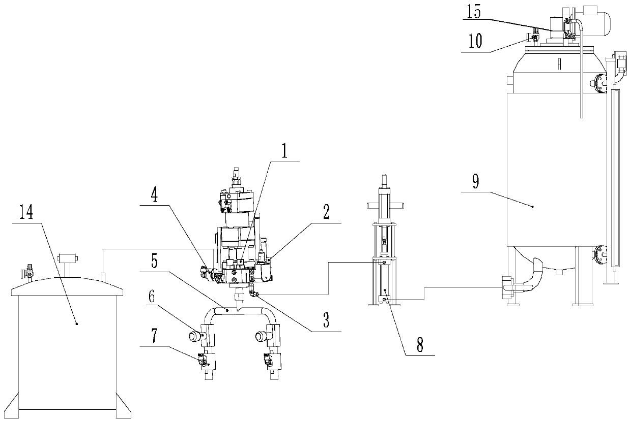
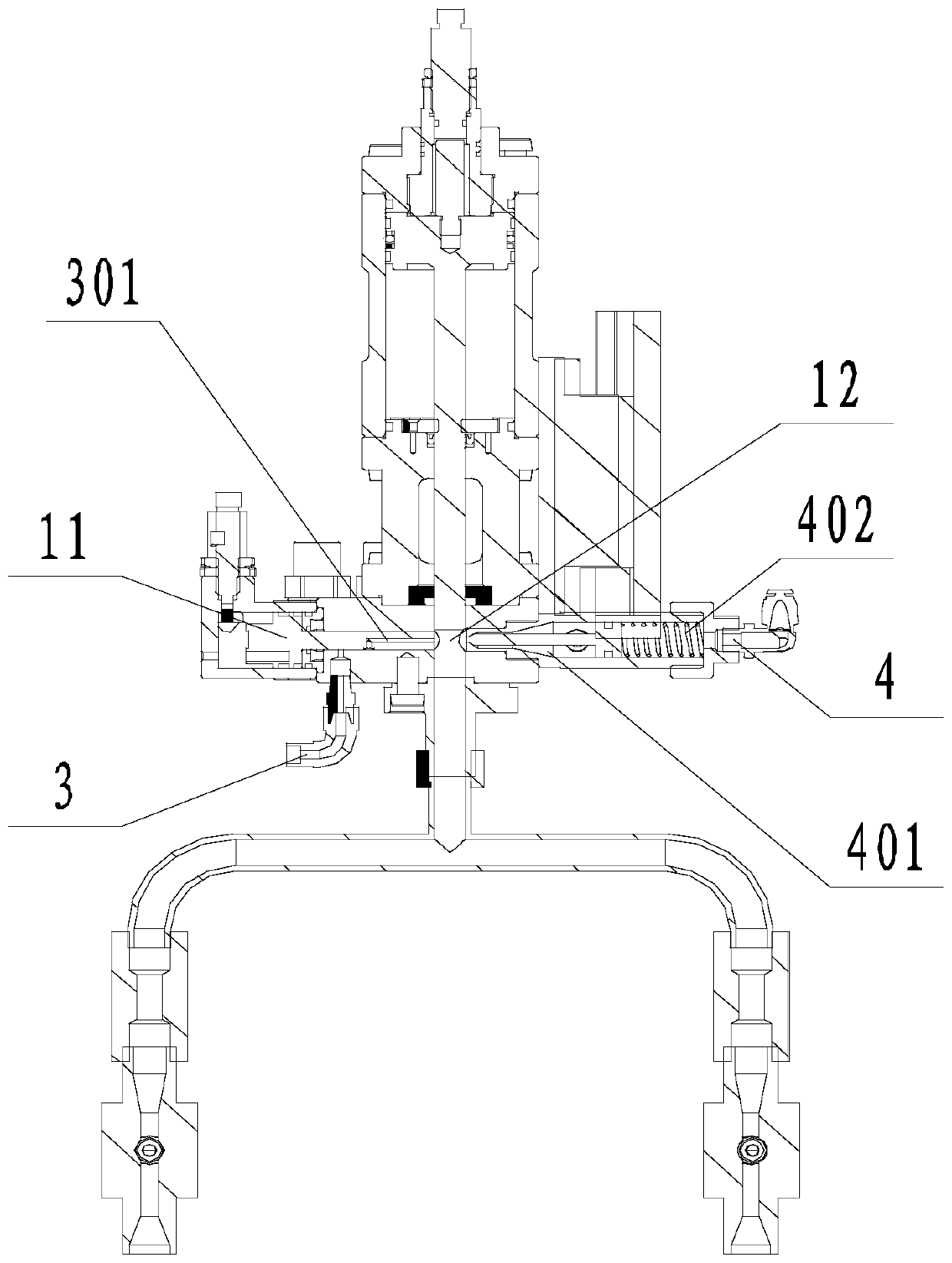
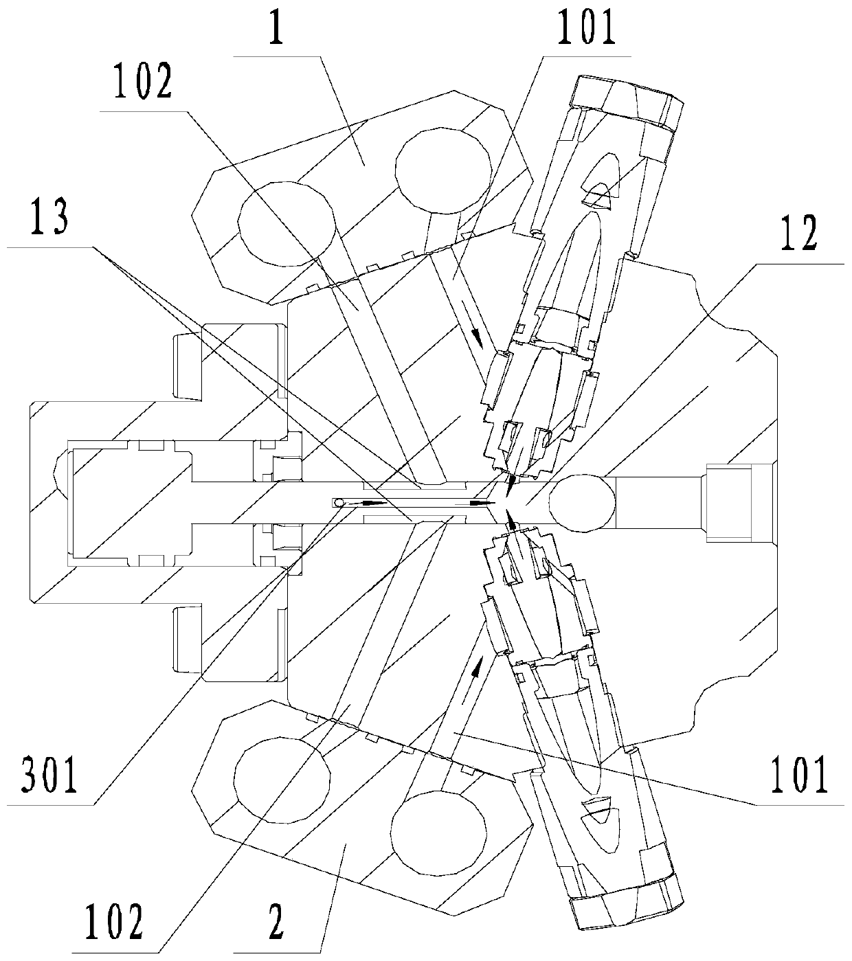
[0039] Such as Figure 1 to Figure 4 The shown polyurethane foaming equipment that can add powder component multi-channel pouring includes gun head body, which is equipped with component A injection device 1 and component B injection device 2, and the inside of the gun head body is set with group A The sub-injection device 1, the small piston 11 and the mixing chamber 12 matched with the component B injection device 2 also include a component C injection device 3, and a component C flow channel matching the component C injection device 3 is set on the small piston 11 301, the C component flow channel 301 is connected to the mixing chamber 12; when the small piston 11 is in the working position, the C component flow channel 301 is in communication with the C component injection device 3; when the small piston 11 is in the stop position, the C component flow The channel 301 is not in communication with the C component injection device 3 . Among them, component C is a premix of ...

Embodiment 2

[0043] Such as Figure 1 to Figure 4 The illustrated polyurethane foaming equipment for multi-channel pouring that can add powder components is based on Example 1. The output end of the gun head body is connected to a flow divider 5, and the flow divider 5 includes two forks. The flow divider 5 includes a base body 501 and a coating layer 502 on the inner wall of the base body 501 , and a split flow regulating valve 6 is set on each branch. The coating 502 is any one of Teflon coating, nano non-stick coating, and metal non-stick coating, or the substrate 501 is directly made of a polytetrafluoroethylene-lined pipe.

[0044] The component A injection device 1 and the component B injection device 2 both include an input flow channel 101 and an output flow channel 102, and also include a circulation mechanism, which is used to make the input flow channel 101 and the output flow channel of the A component injection device 1 102 is connected, and the input flow channel 101 of the ...

Embodiment 3

[0048] Such as Figure 1 to Figure 4 The shown polyurethane foaming equipment that can add powder components to multi-channel pouring, on the basis of any of the above-mentioned embodiments, a positive pressure cleaning device 4 is set on the gun head body, and the positive pressure cleaning device 4 is used to spray the gun head body Positive pressure air is input inside; a negative pressure cleaning device 7 is provided on each branch of the diverter 5, and the negative pressure cleaning device 7 is used to create negative pressure in the corresponding branch. It also includes a release agent injecting device 14 connected to the positive pressure cleaning device 4, and the positive pressure cleaning device 4 is used to inject the release agent into the inner wall of the diverter.

[0049] Preferably, the positive pressure cleaning device 4 is located on the opposite side of the C component flow channel 301, and the positive pressure cleaning device 4 includes a sealing pisto...


PUM


Abstract

The invention discloses polyurethane foaming equipment capable of adding powder components for multi-channel pouring. The equipment comprises a gun head body, a component A injection device and a component B injection device are arranged on the gun head body, a small piston and a mixing cavity which are matched with the component A injection device and the component B injection device are arrangedin the gun head body, the equipment further comprises a component C injection device used for injecting a powder component and B material premix, the small piston is provided with a component C flowing channel matched with the component C injection device, and the component C flowing channel communicates with the mixing cavity. When the small piston is at the working station, the component C flowing channel communicates with the component C injection device; and when the small piston is in the stopping position, the component C flowing channel does not communicate with the component C injection device. The polyurethane foaming equipment is used for solving the problems that in the prior art, the cast-in-place foaming operation of a polyurethane road bed block is greatly influenced by weather and environment, operation cannot be carried out in a humid environment and predrying is needed, thereby achieving the purposes of reducing the requirement on the operation environment by adding the material C and improving the operation efficiency.

Description

technical field [0001] The invention relates to the field of polyurethane ballast beds, in particular to polyurethane foaming equipment capable of adding powder components and casting in multiple channels. Background technique [0002] The track bed is an important part of the track and the foundation of the track frame. Including sleepers and ballast stones, the main function is to support the sleepers, evenly transmit the huge pressure on the upper part of the sleepers to the roadbed surface, and fix the position of the sleepers, prevent the longitudinal or lateral movement of the sleepers, greatly reduce the deformation of the roadbed, and ease the wheel load of rolling stock. Impact on rails for easy drainage. [0003] The traditional ballast bed is divided into ordinary ballast bed, asphalt track bed and concrete monolithic track bed. Ordinary ballast bed is usually piled up by hard crushed stones with a certain particle size, gradation and strength, and graded pebble...

Claims


Application Information

Patent Timeline
IPC IPC(8): B08B9/032B08B9/035B05B15/50B05B14/00E01B27/02
CPCB05B14/00B05B15/50B08B9/0328B08B9/035E01B27/02
Inventor 鲁玉凡谭正亮鲁云飞邓理坤孙永琦黄鑫
Owner 成都东日瑞姆机械有限公司
Why Eureka
Try Eureka