Control system of live-working robot and live-working robot

A control system and live work technology, applied in the direction of program control manipulators, manipulators, manufacturing tools, etc., can solve the problems of high-risk operation labor volume, high-pressure working environment of operators, etc., to facilitate connection and maintenance, avoid economic losses, and reduce weight. Effect

Pending Publication Date: 2020-07-28
山东乐普韦尔自动化技术有限公司
View PDF9 Cites 17 Cited by
  • Summary
  • Abstract
  • Description
  • Claims
  • Application Information

AI Technical Summary

Problems solved by technology

[0004] The invention provides a live working robot control system and a live working robot, which are used to solve the problems of high pressure and high risk in t...

Method used


Image

  • Control system of live-working robot and live-working robot
  • Control system of live-working robot and live-working robot
  • Control system of live-working robot and live-working robot

Examples


Embodiment 1

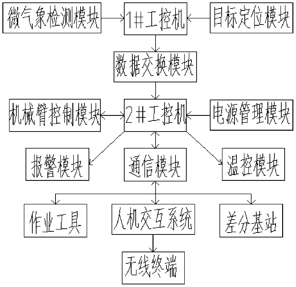
[0038] A live working robot control system, such as figure 1 As shown, it includes a main control system module and a data exchange module. The main control system module includes 1# industrial computer and 2# industrial computer. The model of the industrial computer is AAEON PICO-ITX. communication to realize data interaction; the control system also includes a target positioning module, a micro-weather detection module, a manipulator control module, a power management module and a communication module.

[0039] The 1# industrial computer is connected with the target positioning module and the micro-weather detection module; the target positioning module is used to scan and model the work space, obtain the image information parameters of the work scene, and determine the position of the operation object in the robot coordinate system The target positioning module includes a differential GPS module, a fixed visible light camera, a binocular camera, and a laser scanning sensor,...

Embodiment 2

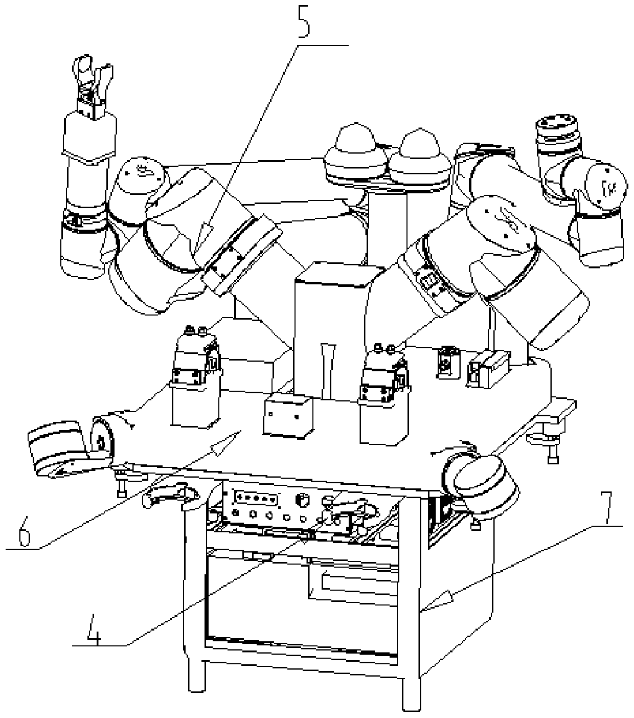
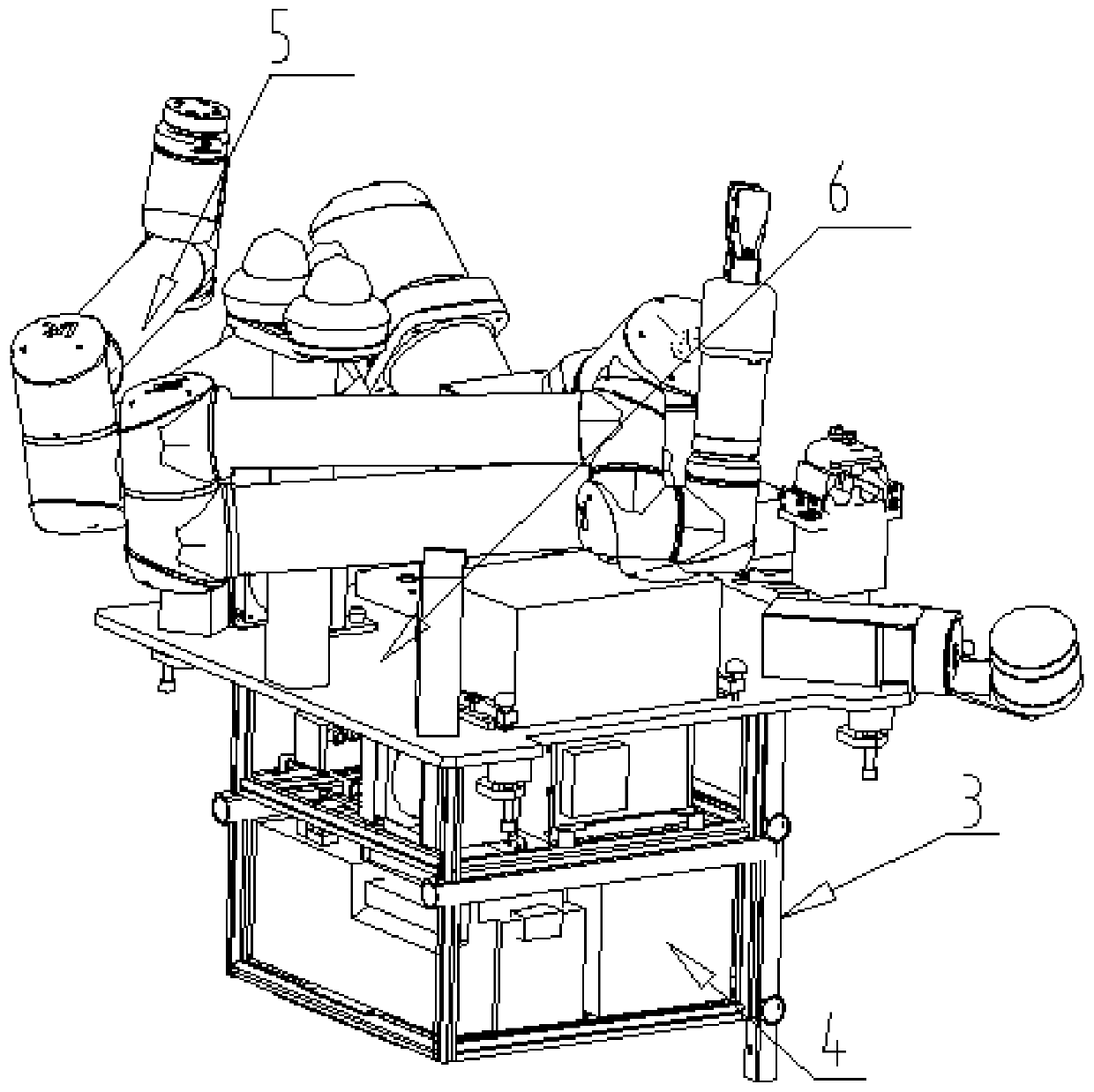
[0049] On the basis of Embodiment 1, a live working robot, such as Figure 2-Figure 3 As shown, it includes the above-mentioned live working robot control system 4, and also includes a frame 3 for installing the control system 4, a mechanical arm module 5, a reference plate table top module 6 and a housing assembly 7; the reference plate table top module 6 includes a heat dissipation module 6-9, lithium battery pack 6-2, tool quick change device 6-5, adapter plate 6-8, reference plate 6-1, clamping mechanism 6-7, laser positioning module 6-4, sleeve recovery module 6-6, wire clamp 6-3, mechanical arm bracket 6-10 and video monitoring module 6-11, wherein, tool quick change device 6-5, reference plate 6-1, laser positioning module 6-4 and wire clamp Tooling 6-3, etc. need to be accurately positioned, and the positioning is carried out through the seam.

[0050] Such as image 3 , Figure 5-Figure 6 As shown, the upper side of the frame 3 is provided with a reference plate 6-...


PUM


Abstract

The invention provides a control system of a live-working robot. The control system comprises a master control system module and a data exchange module. The master control system module comprises a first industrial personal computer and a second industrial personal computer. The industrial personal computers communicate through the data exchange module to achieve data interaction. The control system further comprises a target positioning module, a micro weather detection module, a mechanical arm control module, a power supply management module and a communication module. The invention furtherprovides the live-working robot which comprises the control system of the live-working robot and further comprises a frame for mounting the control system, a mechanical arm module, a datum plate tableboard module and a shell assembly. The datum plate table board module comprises a heat-dissipating module, a lithium battery pack, a tool quick change device, an adapter plate, a datum plate, a clamping mechanism, a laser positioning module, a sleeve recycling module, a cable clamp tool, a mechanical arm bracket and a video monitoring module.

Description

technical field [0001] The invention belongs to the technical field of live robots, in particular to a control system of a live working robot and a live working robot. Background technique [0002] The traditional live working is that the operator uses high-voltage working tools to work; the human-machine separation live working robot, that is, the robot works at high altitude, and the operator remotely controls the robot to work on the ground; the human-machine collaborative live working robot, that is, the robot and the working robot Personnel carry out collaborative live work in different insulated buckets of bucket arm trucks; hydraulic live work robots complete live work through the mutual cooperation of hydraulic arms. [0003] In addition, the traditional live-line work has a large labor load, high risk factor, harsh working conditions, frequent personal injury accidents, and low work efficiency; the human-machine separation type live-work robot has complicated operat...

Claims


Application Information

Patent Timeline
IPC IPC(8): B25J9/08B25J9/16B25J13/08B25J11/00
CPCB25J9/08B25J9/1679B25J9/1664B25J9/1697B25J13/087B25J11/00
Inventor 马孝林孙昊宁中锋刘笑鹏张恒
Owner 山东乐普韦尔自动化技术有限公司
Why Eureka
Try Eureka