Solid particle heat exchange system for fluidized bed

A technology of fluidized bed heat exchangers and solid particles, applied in fluidized bed heat exchangers, solar heating systems, indirect heat exchangers, etc., can solve problems such as lack of comprehensive description, reduce heat exchange losses, ensure Effects of safety and heat loss reduction

Inactive Publication Date: 2020-07-28
DONGFANG BOILER GROUP OF DONGFANG ELECTRIC CORP
View PDF9 Cites 1 Cited by
  • Summary
  • Abstract
  • Description
  • Claims
  • Application Information

AI Technical Summary

Problems solved by technology

However, in view of the special requirements of frequent start-stop and rapid start-up of photothermal power plants, the solid particle heat exchange system is required to have its own preheating function and be able to be put into operation in a short period of time. This is not fully described in the literature

Method used


Image

  • Solid particle heat exchange system for fluidized bed
  • Solid particle heat exchange system for fluidized bed

Examples


Embodiment 1

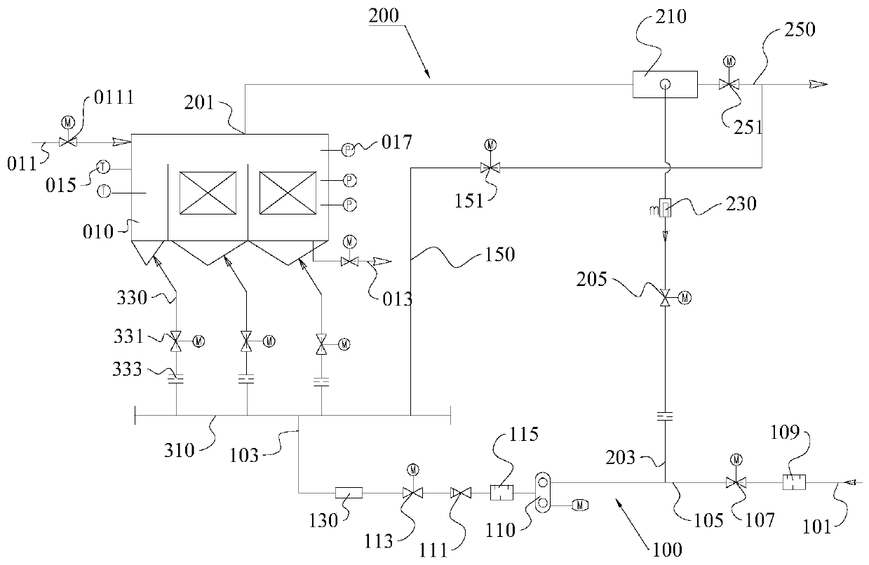
[0044] This embodiment provides a fluidized bed solid particle heat exchange system, please refer to figure 1 , this fluidized bed solid particle heat exchange system includes a fluidized bed heat exchanger 010, an air supply part and a return part;

[0045] The fluidized bed heat exchanger 010 includes a solid particle flow channel having a solid particle inlet 011 and a solid particle outlet 013 .

[0046] Wherein, the air supply part includes an air supply pipeline 100 provided with a heater 130 , the air supply pipeline 100 has a first air inlet end, a first air outlet end 103 and an air outlet between the first air inlet end and the first air outlet end 103 The air mixing section 105 between them;

[0047] The return part includes a return pipeline 200, and the return pipeline 200 has a second air inlet end 201 and a second air outlet end 203;

[0048] The first air inlet port is connected to the fresh air inlet 101 , and fresh air is introduced from the fresh air inlet...

Embodiment 2

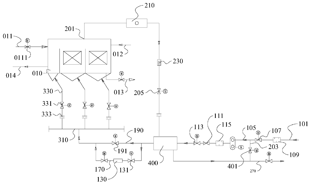
[0071] This embodiment provides a fluidized bed solid particle heat exchange system, please refer to figure 2 , this fluidized bed solid particle heat exchange system includes a fluidized bed heat exchanger 010, an air supply part and a return part;

[0072] The fluidized bed heat exchanger 010 includes a solid particle flow channel having a solid particle inlet 011 and a solid particle outlet 013 .

[0073] Wherein, the air supply part includes an air supply pipeline 100 provided with a heater 130 , the air supply pipeline 100 has a first air inlet end, a first air outlet end 103 and an air outlet between the first air inlet end and the first air outlet end 103 The air mixing section 105 between them;

[0074] The return part includes a return pipeline 200, and the return pipeline 200 has a second air inlet end 201 and a second air outlet end 203;

[0075] The first air inlet port is connected to the fresh air inlet 101 , and fresh air is introduced from the fresh air inlet ...


PUM


Abstract

The invention provides a solid particle heat exchange system for a fluidized bed, and belongs to the field of heat exchangers. The solid particle heat exchange system for the fluidized bed comprises afluidized bed heat exchanger, an air supply part and a reflux part; the air supply part comprises an air supply pipeline which is provided with a heat; the air supply pipeline is provided with a first air inlet end, a first air outlet end and an air mixing section positioned between the first air inlet end and the first air outlet; the reflux part comprises a reflux pipeline; the reflux pipelineis provided with a second air inlet end and a second air outlet end; the first air inlet end is connected with a fresh air inlet; the first air outlet end communicates with a fluidizing air inlet of the fluidized bed heat exchanger; a fluidizing air outlet of the fluidized bed heat exchanger communicates with the second air inlet end; the second air outlet end is connected with the air mixing section; and the air mixing section is used for mixing the gas introduced from the first air inlet end and the gas flowing out from the second air outlet end. Preheating and temperature rising of the fluidized bed heat exchanger and prepacking can be completed effectively, so that high-temperature particles are prevented from entering the fluidized bed heat exchanger to affect the service life of theheat exchanger because of rising temperature too fast.

Description

technical field [0001] The invention relates to the field of heat exchangers, in particular to a fluidized bed solid particle heat exchange system. Background technique [0002] sCO with high efficiency and low cost potential with temperature above 700°C 2 Solar thermal power generation system is currently a hotspot in international solar thermal power generation research. The European Union and the US DOE launched the technology research program in 2018. with sCO 2 The representative solar thermal power generation system mainly consists of high focal ratio concentrators, high temperature absorbers, supercritical CO 2 Heat Exchanger and Supercritical CO 2 Turbines and other four parts. [0003] The solar energy utilization technology that uses solid particles as the heat transfer medium can heat up to 900-1000°C due to the heat absorption of the particles, breaking through the operating temperature of about 560°C of traditional molten salt, and is a high-temperature sup...

Claims


Application Information

Patent Timeline
Patent Type & Authority Applications(China)
IPC IPC(8): F28D13/00F28F27/00F24S60/00
CPCF28D13/00F28F27/00F24S60/00Y02E10/40
Inventor 李有霞黄敏孙登科巩李明
Owner DONGFANG BOILER GROUP OF DONGFANG ELECTRIC CORP
Why Eureka
Try Eureka