
Automatic assembling equipment for semi-finished product of micro loudspeaker

A micro-speaker, automatic assembly technology, applied in the direction of sensors, electrical components, etc., can solve the problems of complex structure, large area and low machining accuracy of assembly equipment, and achieve the effect of simplifying the structure, improving efficiency and improving production efficiency.

Active Publication Date: 2020-07-28
WENZHOU POLYTECHNIC
View PDF11 Cites 1 Cited by
  • Summary
  • Abstract
  • Description
  • Claims
  • Application Information

AI Technical Summary

Problems solved by technology

[0005] Aiming at the deficiencies of the prior art, the present invention provides an automatic assembly equipment for semi-finished products of miniature loudspeakers with high finished product quality, reasonable station allocation, and smooth connection, which solves the problems of complex structure, large footprint, low processing accuracy and processing efficiency of the prior art assembly equipment. too low problem

Method used


Image

  • Automatic assembling equipment for semi-finished product of micro loudspeaker
  • Automatic assembling equipment for semi-finished product of micro loudspeaker
  • Automatic assembling equipment for semi-finished product of micro loudspeaker

Examples


Embodiment 1

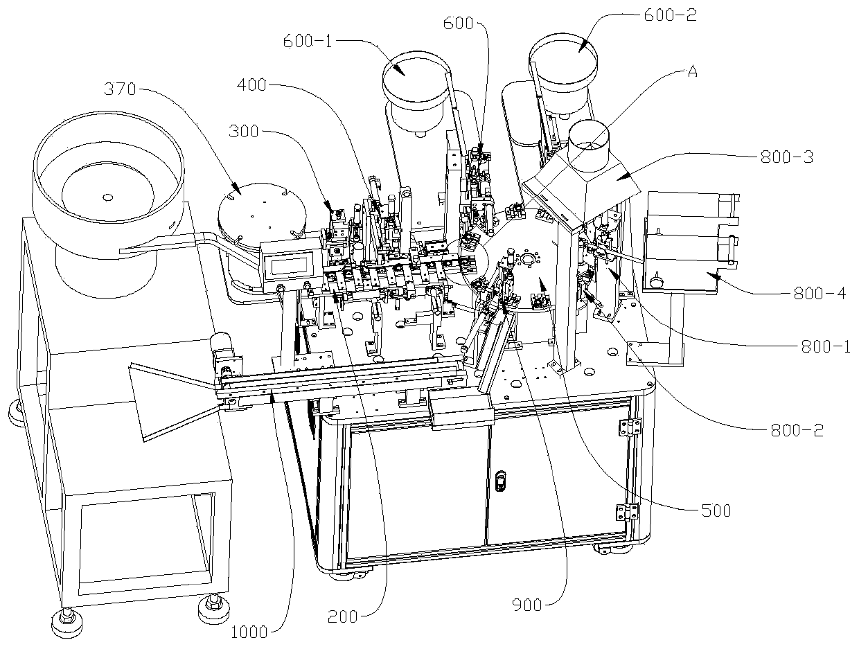
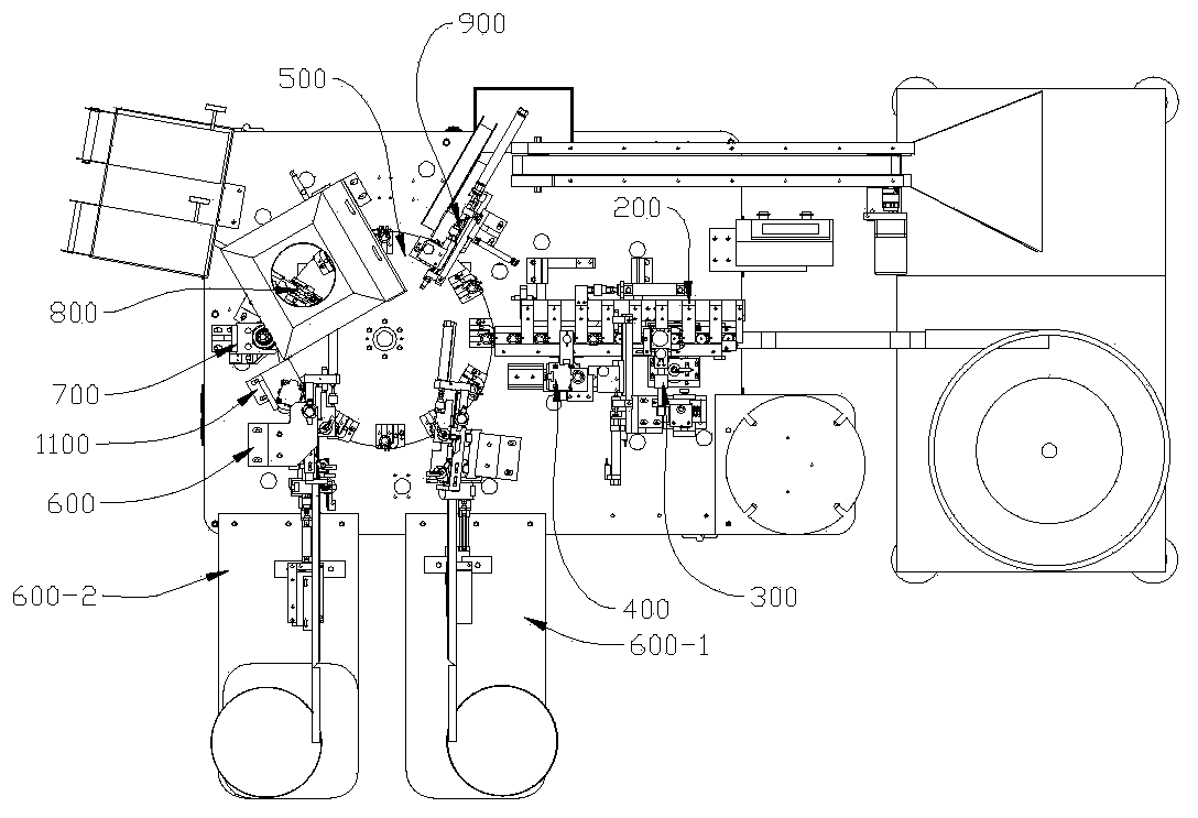
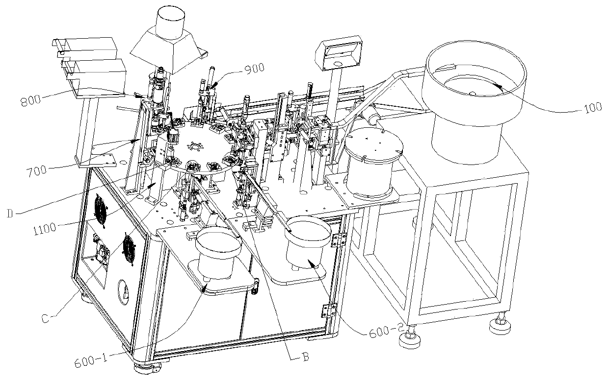
[0081] like Figure 36 As shown, this embodiment provides a kind of automatic assembly equipment for semi-finished products of micro-speakers, which involves a total of four parts for the plastic casing 1, the vibrating diaphragm 2, and the two terminals of terminal one 301 and terminal two 302, combined with Figure 1-Figure 3 As shown, the processing process includes feeding plastic shell 1, dispensing glue, upper vibrating diaphragm 2, pressure gluing, upper terminal 1 301 and terminal 2 302, terminal pressing and positioning, terminal heat riveting, terminal spot welding, taking out materials and other steps. In order to simplify the automatic assembly production line and improve the smoothness of the connection between each processing procedure, so that each processing procedure can be kept at the same working rhythm, this embodiment divides the specific processing steps in the above-mentioned processing process into two major processes. The first station includes plasti...

Embodiment 2

[0112] like Figure 29 As shown, the difference between this embodiment and the above-mentioned embodiments is that in this embodiment, a flattening and fitting mechanism 1100 is provided after the terminal is loaded and between hot riveting processing. The flattening and fitting mechanism 1100 includes a seat body 1120, The vertical movement cylinder five 1110 and the guide seat 1121 fixedly installed on the seat body 1120, and a flattening joint head 1130 is slid through the guide seat 1121, between the flattening joint head 1130 and the piston rod of the longitudinal movement cylinder five 1110 Fixedly connected by a clamping block 1101 , a position sensor is fixedly installed under the guide seat 1121 and on the seat body 1120 for detecting the descending height of the flattening head 1130 . combine Figure 30 As shown, the bottom of the flattened abutting head 1130 is provided with two abutting parts corresponding to the two metal positioning pins 101 on the plastic shel...


PUM


Abstract

The invention provides automatic assembling equipment for a semi-finished product of a micro loudspeaker. The invention belongs to the field of loudspeaker processing equipment. The automatic assembling equipment comprises a first station by adopting linear conveying and a second station by adopting rotary conveying, and the first station comprises a first feeding mechanism, a dispensing mechanism, a second feeding mechanism, a sheet pressing mechanism and a translation pushing mechanism which are sequentially distributed according to the sequence of working procedures. The second station comprises two third feeding mechanisms, two positioning adjusting mechanisms, a flattening and involution mechanism, a hot riveting mechanism, a first welding mechanism, a second welding mechanism, a material taking mechanism and a rotary disc mechanism which are sequentially distributed according to the procedure sequence. By adopting a conveying mode of combining linear conveying and rotary conveying, the loudspeakers are correspondingly distributed on the linear conveying line or the rotary conveying line according to the characteristics of each processing procedure, and by simplifying, optimizing and splitting each mechanism, the rhythms among the processing mechanisms are consistent, the flow connection is smooth, and the automatic assembly efficiency of the loudspeakers is effectively improved.

Description

technical field [0001] The invention relates to the field of automatic assembly equipment for loudspeakers, in particular to an automatic assembly equipment for semi-finished miniature loudspeakers. Background technique [0002] Loudspeaker, also known as "horn", is a commonly used electroacoustic transducer, which includes a housing, diaphragm, magnet and conductive terminals. There is a micro-speaker currently on the market, which adopts a flat diaphragm, which is flat and cylindrical as a whole, and involves the improvement of the diaphragm structure: it is combined with two conductive terminals at an appropriate position on the surface of the diaphragm of the speaker. This structure can replace the commonly used voice coil wires, simplify the structure and at the same time eliminate the abnormal sound generated by using the voice coil wires and improve the sound quality of the loudspeaker. [0003] For the processing of the above-mentioned improved structure, the assemb...

Claims


Application Information

Patent Timeline
Patent Type & Authority Applications(China)
IPC IPC(8): H04R31/00
CPCH04R31/00
Inventor 黄其祥
Owner WENZHOU POLYTECHNIC
Learn More