
Multi-row wire clamping positioning jig and multi-row wire clamping positioning method

A positioning fixture, clamping and positioning technology, applied in the direction of manufacturing tools, circuit/collector parts, auxiliary devices, etc., can solve problems such as inconvenient operation, easy bending of wires under force, troubles, etc.

Pending Publication Date: 2020-07-31
DONGGUAN SANXIN PRECISION MACHINERY
View PDF0 Cites 0 Cited by
  • Summary
  • Abstract
  • Description
  • Claims
  • Application Information

AI Technical Summary

Problems solved by technology

However, since the mother substrate for high-speed equipment to be welded requires front and back welding wires, the disadvantage of using traditional wire clips is that it needs to replace the fixture twice, and process the two rows of wires twice, which is inconvenient to operate, manually flipped, and now The wire with a large clamp angle is prone to twitching and bending under force, and the variable shape of the cable itself has problems, and it is difficult to position accurately, which will affect the subsequent cutting, stripping, and soldering quality with the circuit board
[0004] Of course, for more than two rows of multi-row wires, for example: four rows or more than four rows of multi-row wires, it is even more troublesome to use the traditional method to process the operation, the operation efficiency is low, the welding quality is not good, and it is difficult to meet the requirements. Product Quality Requirements

Method used


Image

  • Multi-row wire clamping positioning jig and multi-row wire clamping positioning method
  • Multi-row wire clamping positioning jig and multi-row wire clamping positioning method
  • Multi-row wire clamping positioning jig and multi-row wire clamping positioning method

Examples


Embodiment Construction

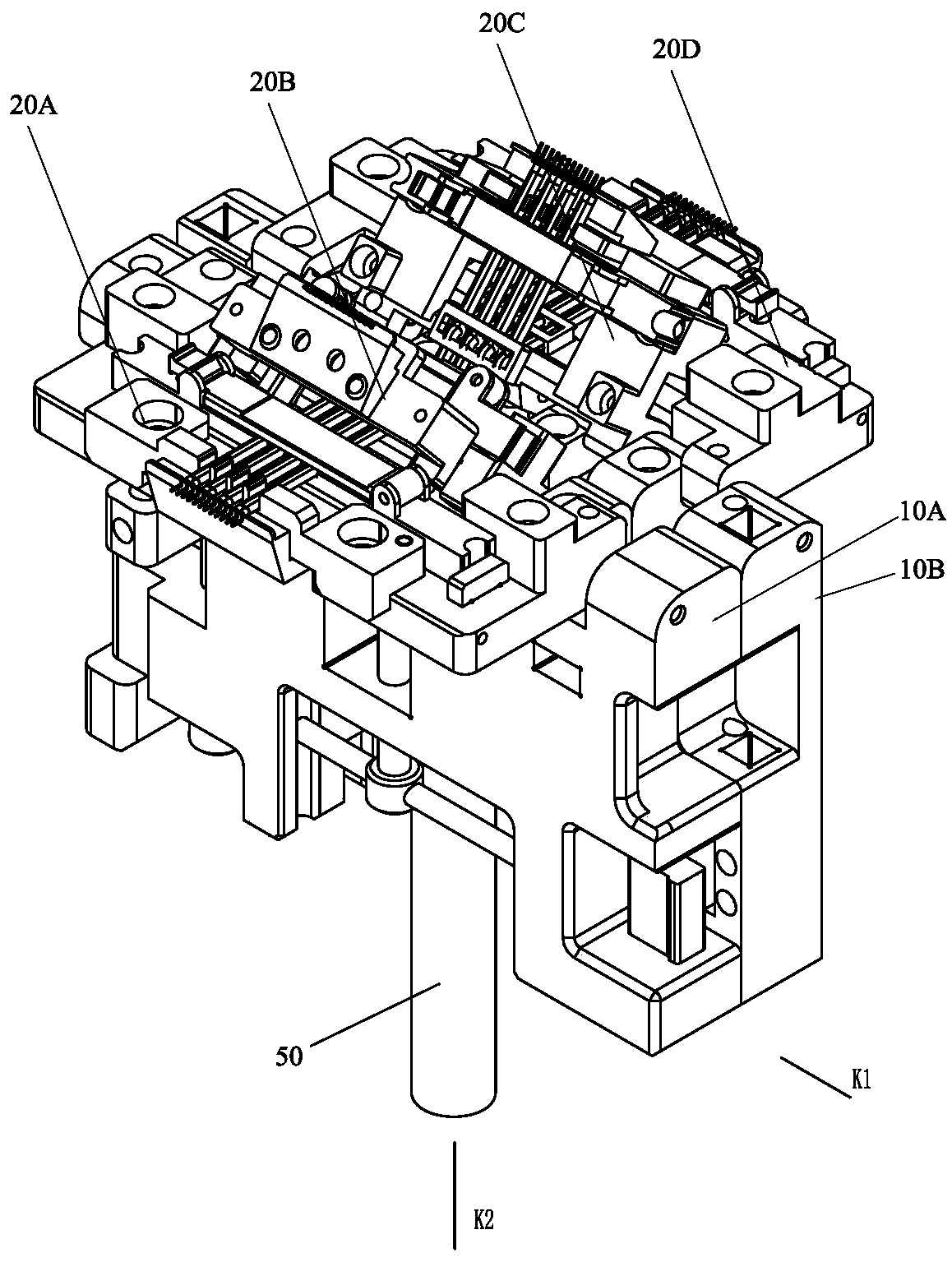
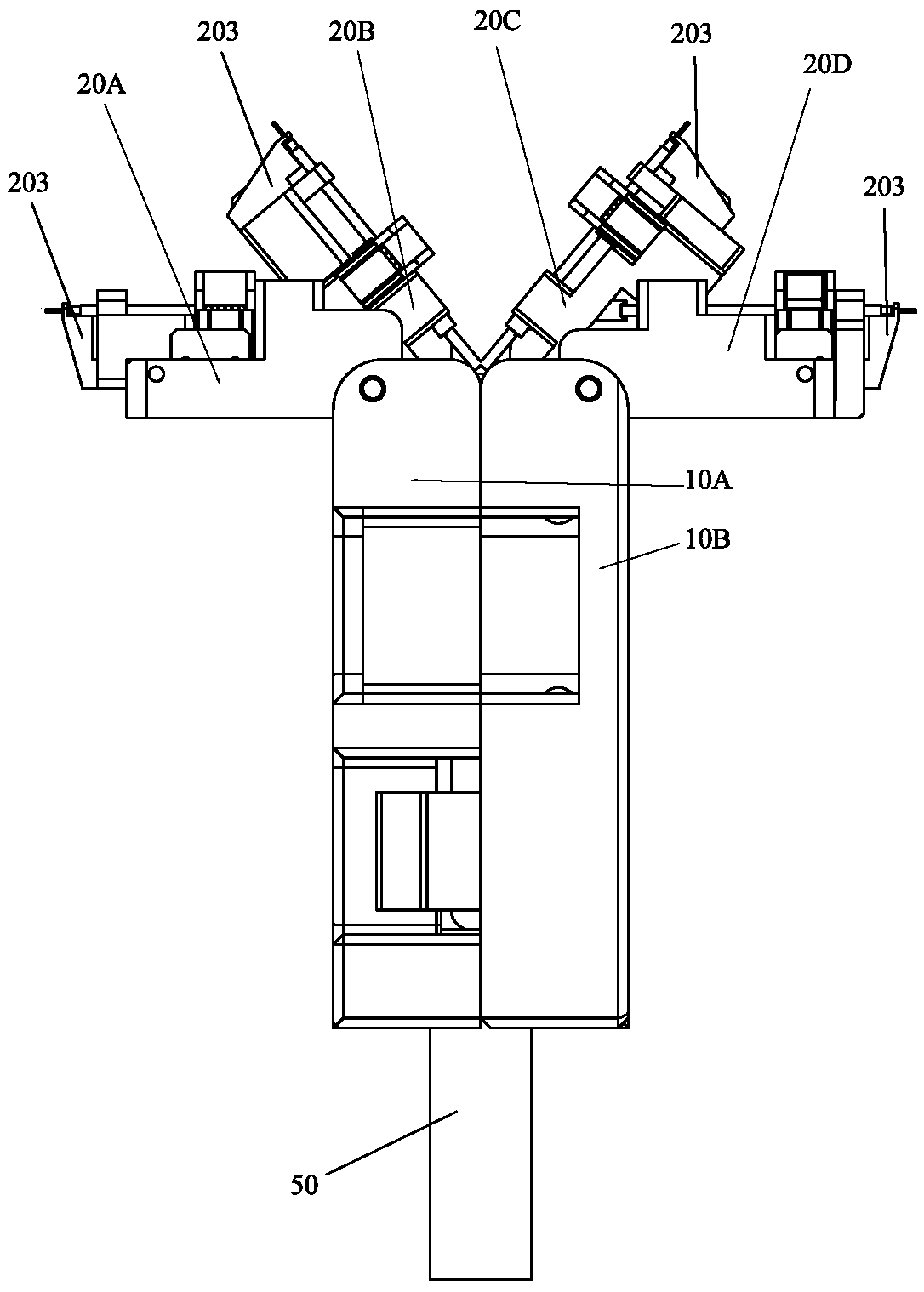
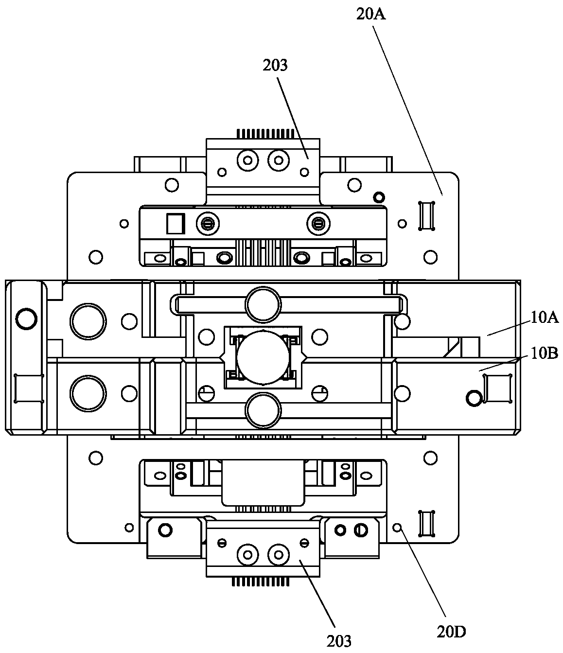
[0060] Please refer to Figure 1 to Figure 18 As shown, it shows the specific structure of the preferred embodiment of the present invention.

[0061] Such as Figure 1 to Figure 4 As shown, a multi-row wire clamping positioning jig includes a left clamping plate 10A, a right clamping plate 10B, a first positioning base 20A, a second positioning base 20B, a third positioning base 20C, a Four positioning base 20D; where:

[0062] The left clamping plate 10A and the right clamping plate 10B can be flipped along the X-axis to realize opening and closing, and after closing, a gap for wire insertion is formed between the left clamping plate 10A and the right clamping plate 10B; the first The positioning base 20A and the second positioning base 20B are respectively arranged at the head end of the left clamping plate 10A and can be flipped along the Y axis relative to the left clamping plate 10A; the third positioning base 20C and the fourth positioning base 20D are respectively a...


PUM


Abstract

The invention discloses a multi-row wire clamping positioning jig and a multi-row wire clamping positioning method. The jig comprises a left wire clamping plate, a right wire clamping plate, a first positioning base, a second positioning base, a third positioning base and a fourth positioning base; the left wire clamping plate and the right wire clamping plate can be turned over along the X axis to be opened and closed; the first positioning base and the second positioning base are arranged at the head end of the left wire clamping plate and can be turned over along the Y axis relative to theleft wire clamping plate; and the third positioning base and the fourth positioning base are arranged at the head end of the right wire clamping plate and can can be turned over along the Y axis relative to the right wire clamping plate. According to the jig and the method, by means of the design, multiple rows of wires can be used in an automatic operation production line, the multiple rows of wires can be positioned to be machined at the same time or machined in batches, and the operation is convenient; and the positioning bases in the jig can be turned over relative to the left wire clamping plate or the right wire clamping plate, so that pulling on the wires is reduced, and the problem of precise machining on the row wires is solved.

Description

technical field [0001] The invention relates to the technology in the field of wire rod processing, in particular to a multi-row wire clamping positioning fixture and a multi-row wire clamping positioning method. Background technique [0002] The use of high-speed data transmission cables is increasing. As the demand for connectivity increases, high-speed cables are required to provide connections between different devices such as routers and switches. A QSFP cable typically includes four SFP cables enclosed in a trunk cable. Such cables are typically manufactured by twisting or binding four SFP cables together. The industry needs to strip the QSFP cables, separate them into double-row cables, arrange them according to the set line sequence, and then solder them to the corresponding circuit board pads of high-speed equipment. [0003] At present, the commonly used jigs for stripping and processing high-speed data transmission cables are 180° plane jigs for processing, or ...

Claims


Application Information

Patent Timeline
IPC IPC(8): B23K37/04B23K37/00H01R43/28
CPCB23K37/00B23K37/0426H01R43/28
Inventor 姚天金
Owner DONGGUAN SANXIN PRECISION MACHINERY
Features
  • Generate Ideas
  • Intellectual Property
  • Life Sciences
  • Materials
  • Tech Scout
  • Unparalleled Data Quality
  • Higher Quality Content
  • 60% Fewer Hallucinations
Learn More