Complex terrain adaptive landing gear of vertical take-off and landing aircraft and landing method of complex terrain adaptive landing gear

A technology of complex terrain and landing gear, applied to vertical take-off and landing aircraft, aircraft, aircraft landers, etc., can solve problems such as poor adaptability, achieve convenience in movement and transportation, reduce operation difficulty, increase recovery rate and safety level Effect

Active Publication Date: 2020-07-31
CHINA AIRPLANT STRENGTH RES INST
View PDF12 Cites 10 Cited by
  • Summary
  • Abstract
  • Description
  • Claims
  • Application Information

AI Technical Summary

Problems solved by technology

[0008] In order to solve the above technical problems, an embodiment of the present invention provides a complex terrain adaptive landing device and landing method for a vertical take-off and landing aircraft, so as to solve the common problem of poor adaptability in the landing process of existing landing devices, and can ensure that the vertical take-off and landing The landing aircraft can land stably in various landing environments such as steps, slopes, uneven ground, sandy ground, soft mud ground, and wading ground, and can improve the landing safety of vertical take-off and landing aircraft

Method used


Image

  • Complex terrain adaptive landing gear of vertical take-off and landing aircraft and landing method of complex terrain adaptive landing gear
  • Complex terrain adaptive landing gear of vertical take-off and landing aircraft and landing method of complex terrain adaptive landing gear
  • Complex terrain adaptive landing gear of vertical take-off and landing aircraft and landing method of complex terrain adaptive landing gear

Examples


specific Embodiment 1

[0093] Specific embodiment 1: Adaptive landing on complex ground

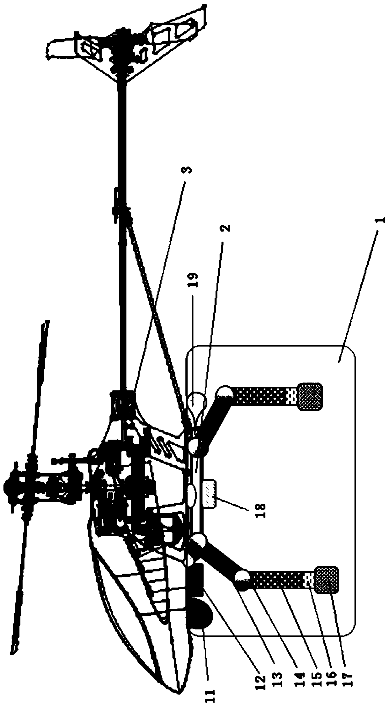
[0094] Before landing, vertical take-off and landing vehicle 3 reaches a certain height range (such as 50m~100m height), and when reaching the height range, vertical take-off and landing vehicle 3 hovers, scan detector 11, terrain recognition camera 12 work, determine whether to land, and large Select a suitable landing site for landing. The scanning detector 11 obtains terrain conditions through point cloud data, and the terrain recognition camera 12 obtains ground material information through images.

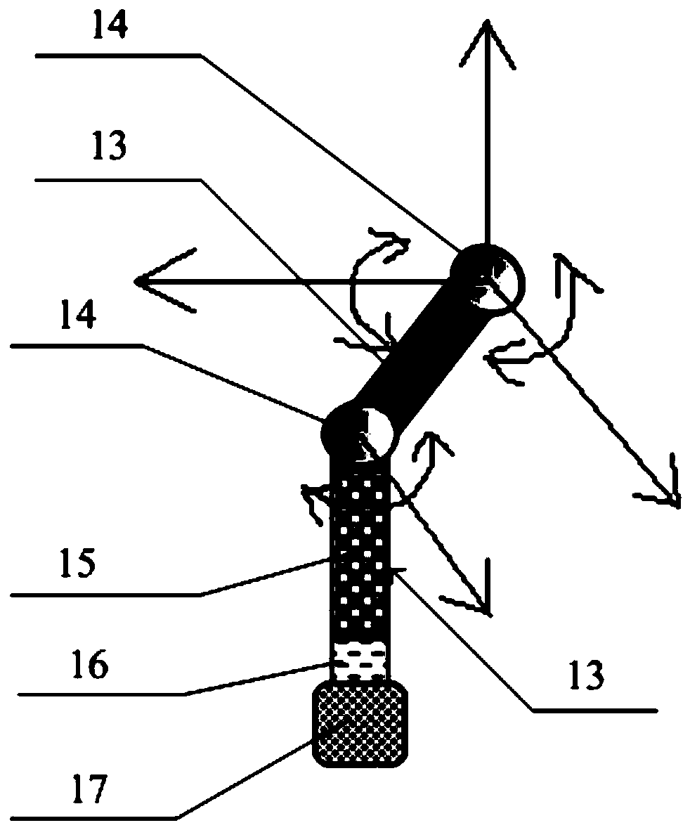
[0095] The flight control system and the landing gear control system determine the landing state and mode of the vertical take-off and landing aircraft 3 through terrain and geological information, and drive the leg link 13 to move by controlling the movable joint 14 to pre-swing to a state suitable for the terrain. Select the specific state of the foot end device 17 according to the ground material. For examp...

specific Embodiment 2

[0097] Specific embodiment 2: emergency crash

[0098] In the case of an emergency crash, the flight control system determines that the vertical take-off and landing aircraft 3 is in a crash state, and when the sinking speed exceeds a certain threshold, the crash airbag 18 is opened, and the complex terrain adaptive landing gear 1 is in a prefabricated initial state ( That is, the intermediate state of the range of motion, ensuring that the feet of multiple landing legs are at the same horizontal position, and that the plane formed is higher than the bottom surface of the crash airbag 18), such as Figure 5 As shown, a schematic diagram of the complex terrain adaptive landing gear of the vertical take-off and landing aircraft provided by the embodiment of the present invention during an emergency crash, Figure 5 The effect of crashing the airbag 18 is shown in the figure.

[0099] After landing, first the crash airbag 18 touches the ground, and then deflates after touching t...

specific Embodiment 3

[0100] Specific embodiment 3: ditching

[0101] When ditching is necessary according to mission requirements or environmental constraints, the landing process is similar to "Example 1: Adaptive Landing on Complicated Ground". Landing starts under the control of the flight control system, and the complex terrain adaptive landing gear 1 is in the prefabricated initial state.

[0102] When approaching the water surface, the altitude of the vertical take-off and landing aircraft 3 is determined by scanning the detector 11 and the flight control system, and as the control signal for the opening of the floating airbag 19, the floating airbag 19 is opened to provide buoyancy and avoid sinking into the water. Its state is as follows Figure 6 As shown, it is a schematic diagram of the complex terrain adaptive landing gear of the vertical take-off and landing aircraft provided by the embodiment of the present invention when ditching, Figure 6 Show the action effect of floating air ba...


PUM


Abstract

The embodiment of the invention discloses a complex terrain adaptive landing gear of a vertical take-off and landing aircraft and a landing method of the complex terrain adaptive landing gear. The device comprises at least two landing legs, two movable joints, a scanning detector, a terrain recognition camera and load sensors, wherein upper connecting rods in the landing legs are connected with anundercarriage adapter frame through the movable joints, the upper connecting rods are connected with lower connecting rods through the movable joints, buffer mechanisms are installed in the lower connecting rods, foot end devices are installed at the tail ends of the landing legs, and load sensors are located between the lower connecting rods and the foot end devices; the two movable joints are used for controlling the moving postures of the upper connecting rods and the lower connecting rods respectively; the upper end of the load sensor is connected with the buffer mechanism, and the lowerend is connected with the foot end device; the scanning detector and the terrain recognition camera are mounted below the vertical take-off and landing aircraft; and the load sensors are used for measuring the ground load of the landing legs after the landing legs touch the ground, and controlling the posture of the landing legs by feeding back the ground load of the landing legs to a flight control system. The device disclosed by the embodiment of the invention solves the problem that an existing landing gear is generally poor in adaptability in the landing process.

Description

technical field [0001] The present application relates to but is not limited to the technical field of vertical take-off and landing aircraft landing gear, especially a complex terrain adaptive landing gear for vertical take-off and landing aircraft and its landing method. Background technique [0002] Due to the characteristics of vertical take-off and landing, fixed-point hovering in the air, low-speed flight, low-altitude and ultra-low-altitude flight, in-situ steering, and flight in any direction, the vertical take-off and landing aircraft is limited in take-off and landing sites, and the flying space is small, requiring low-altitude and low-speed tasks. As an ideal aircraft, it has broad application prospects. As an important part of the vertical take-off and landing aircraft, the landing gear plays a supporting role when the helicopter is parked and gliding on the ground, and also plays a role in absorbing the energy generated by the vertical descent speed when landing...

Claims


Application Information

Patent Timeline
Patent Type & Authority Applications(China)
IPC IPC(8): B64C25/62B64D45/06B60F5/02B64C29/00B64C25/56
CPCB64C25/62B64D45/06B60F5/02B64C29/00B64C25/56Y02T50/40
Inventor 任佳王计真刘小川王彬文牟让科
Owner CHINA AIRPLANT STRENGTH RES INST
Why Eureka
Try Eureka