Eureka AIR delivers breakthrough ideas for toughest innovation challenges, trusted by R&D personnel around the world.

Self-holding steel bar connector

A technology of steel bar connectors and steel bars, which is applied to structural elements, building components, building reinforcements, etc., can solve the problems of connection efficiency and effect influence, project progress impact, operation trouble, etc. Production-friendly effects

Inactive Publication Date: 2020-07-31
陶闻钟
View PDF9 Cites 0 Cited by
  • Summary
  • Abstract
  • Description
  • Claims
  • Application Information

AI Technical Summary

Problems solved by technology

If the original or traditional construction method is followed, welding is usually used to weld the two rebars that need to be connected to each other at the ends during the construction of the steel skeleton. This method has the following self-evident shortcomings: First, because welding equipment such as electric welding machines need power support, they are critical to the construction site. For example, the power supply must be led to the welding equipment at the butt joint station of the steel bar through cables or similar feeder lines, and the power supply must be led to The work of welding equipment is both troublesome and unsafe; secondly, because welding needs to be operated by qualified personnel, it is also critical to the operators; thirdly, due to the relatively low efficiency of welding, the progress of the project will be affected Fourth, the welding workers have a high intensity of operation, and it is difficult to guarantee the consistency of welding quality, because the quality of welding is not only affected by environmental factors, but also by factors such as welding personnel's experience, sense of responsibility and even emotion Fifthly, due to the fact that electric welding cannot be used to perform butt welding on the ends of steel bars in open and unsheltered places in cloudy weather, especially in rainy weather, in addition to being picky about the weather, it also affects the progress of the project
[0004] The use of steel bar connectors can avoid the above-mentioned shortcomings to a large extent, and all technical information related to the aforementioned steel bar connectors can be seen in the published Chinese patent documents, such as "a connection assembly for steel bars" recommended by CN208830600U for example " and CN210032349U provide "reinforcement quick connector", because these two patent structures are split type, that is, composed of the first cylindrical sleeve, the second cylindrical sleeve and the sealing connecting sleeve, when in use, will need to be docked One end of one of the two steel bars is inserted into the first cylindrical sleeve cavity of the first cylindrical sleeve with thread on the inner wall, and one end of the other steel bar in the two steel bars is inserted into the same thread on the inner wall In the second cylindrical sleeve cavity of the second cylindrical sleeve, and the aforementioned first cylindrical sleeve and the opposite end of the second cylindrical sleeve are connected by the aforementioned sealed connection sleeve assembly, thus not only the connection efficiency and effect are affected , and the operation is relatively cumbersome
[0005] Typical such as CN204878162U introduces "a locking sleeve structure for quick connection of reinforced steel rods", through the reading of the specification No. 0011 to 0013 of the patent, it can be seen that although it has the advantages of convenient processing of the inner tapper sleeve and the outer taper sleeve Advantages, but the overall structure is relatively complicated and the operation is still cumbersome due to the need to screw the inner taper sleeve and the outer taper sleeve together as a whole.

Method used


Image

  • Self-holding steel bar connector
  • Self-holding steel bar connector

Examples


Embodiment Construction

[0021] In order to understand the technical essence and beneficial effects of the present invention more clearly, the applicant will describe in detail the following examples, but the descriptions of the examples are not intended to limit the solutions of the present invention. Equivalent transformations that are only formal but not substantive should be regarded as the scope of the technical solution of the present invention.

[0022] In the following descriptions, all concepts involving up, down, left, right, front and rear directionality or azimuth are based on the position state of the picture being described, so it cannot be understood as a reference to this Special limitations on the technical solutions provided by the invention.

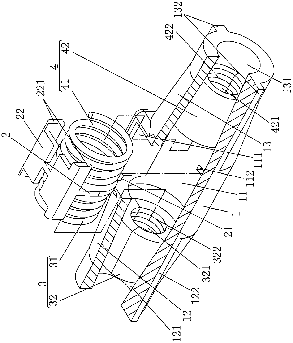
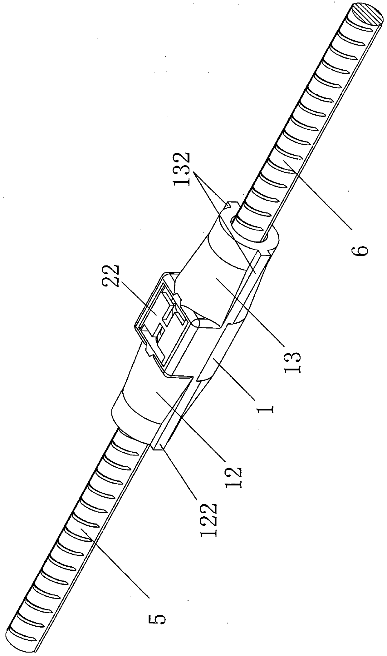
[0023] See figure 1, shows the sleeve base 1, the sleeve base 1 has a sleeve base cavity 11, one side of the sleeve base cavity 11 is formed with a sleeve base cavity opening 111 communicating with the outside world, and in the sleeve There ...


PUM


Abstract

The invention provides a self-holding steel bar connector. The self-holding steel bar connector comprises a sleeve base body, a sleeve base body cavity partition plate and a first steel bar end self-holding mechanism, wherein the sleeve base body is provided with a sleeve base body cavity; a sleeve base body cavity opening communicating with the outside is formed in one side of the sleeve base body cavity; a first conical pipe section extends from the left end of the sleeve base body; a first conical pipe section cavity communicates with the sleeve base body cavity; a second conical pipe section extends from the right end of the sleeve base body; a second conical pipe section cavity communicates with the sleeve base body cavity; the large-diameter ends of the first conical pipe section andthe second conical pipe section face the sleeve base body cavity; the sleeve base body cavity partition plate is inserted in the middle of the sleeve base body and is matched with the sleeve base body cavity opening in a covering mode; and the first steel bar end self-holding mechanism is arranged in the sleeve base body cavity and the first conical pipe section cavity at the position corresponding to the left side of the sleeve base body cavity partition plate, and the second steel bar end self-holding mechanism is arranged in the sleeve base body cavity and the second conical pipe section cavity at the position corresponding to the right side of the sleeve base body cavity partition plate. According to the self-holding steel bar connector, the structure is simplified, and manufacturingis convenient; the construction efficiency is improved, and the operation intensity is reduced; connection is reliable; and the project progress is guaranteed.

Description

technical field [0001] The invention belongs to the technical field of building components, and in particular relates to a self-embracing steel bar connector. Background technique [0002] From the definition of the aforementioned steel bar connector, it can be known that it is used to connect the ends of two steel bars, and the aforementioned steel bar mainly refers to rebar. [0003] As known in the industry, all kinds of construction facilities on the ground, underground and even underwater generally need to use reinforced concrete, and reinforced concrete cannot be separated from the aforementioned rebar. Before the concrete is poured, a steel skeleton needs to be constructed (construction workers are used to calling it "rebarning"). If the original or traditional construction method is followed, welding is usually used to weld the two rebars that need to be connected to each other at the ends during the construction of the steel skeleton. This method has the following ...

Claims


Application Information

Patent Timeline
IPC IPC(8): E04C5/16
CPCE04C5/165
Inventor 陶闻钟
Owner 陶闻钟
Why Eureka
Eureka Blog
Learn More