Optical fiber laser mode decomposition method based on phase recovery, and implementation device thereof

A mode decomposition and fiber laser technology, which is applied in the direction of testing optical fiber/optical waveguide equipment, measuring devices, photometry, etc., can solve the problems of sensitive initial value and easy to fall into local optimum of numerical analysis method, so as to avoid interference and solve phase Measurement tediousness, effects of increased speed and accuracy

Active Publication Date: 2020-07-31
NANJING UNIV OF SCI & TECH
View PDF5 Cites 7 Cited by
  • Summary
  • Abstract
  • Description
  • Claims
  • Application Information

AI Technical Summary

Problems solved by technology

[0004] The object of the present invention is to provide a fiber laser mode decomposition method based on phase recovery and its implementation device, which is not only insensitive to the influence of aberration, but also solves the problem that the traditional numerical analysis method (SPGD) is easy to fall into local problems due to its sensitivity to the initial value. The optimal problem has increased the number of mode decompositions from the original three modes to the current dozen modes

Method used


Image

  • Optical fiber laser mode decomposition method based on phase recovery, and implementation device thereof
  • Optical fiber laser mode decomposition method based on phase recovery, and implementation device thereof
  • Optical fiber laser mode decomposition method based on phase recovery, and implementation device thereof

Examples


Embodiment 1

[0073] Experimental light path such as figure 1 As shown, the first lens 4, the first mirror 5, the second mirror 6, and the second lens 7 form a 4F confocal system, wherein the first lens 4 is a microscopic objective lens with a focal length of 8.5mm, and the second lens 7 is Objective lens with a focal length of 300mm. The optical fiber 2 to be tested is a 20\400mm optical fiber, and the detector 12 is a light intensity detector, that is, a CCD camera.

[0074] Couple the laser light of fiber laser 1 with a wavelength of 1066nm into the optical fiber 2 to be tested. At this time, the intensity distribution of the laser light emitted from the fiber port should be LP 01 mold. After the laser light is emitted, it passes through the first lens 4 , wherein the output port of the optical fiber 2 to be tested is on the object focal plane of the first lens 4 . After passing through the first lens 4 , the laser light is reflected by the first reflector 5 and the second reflector ...


PUM


Abstract

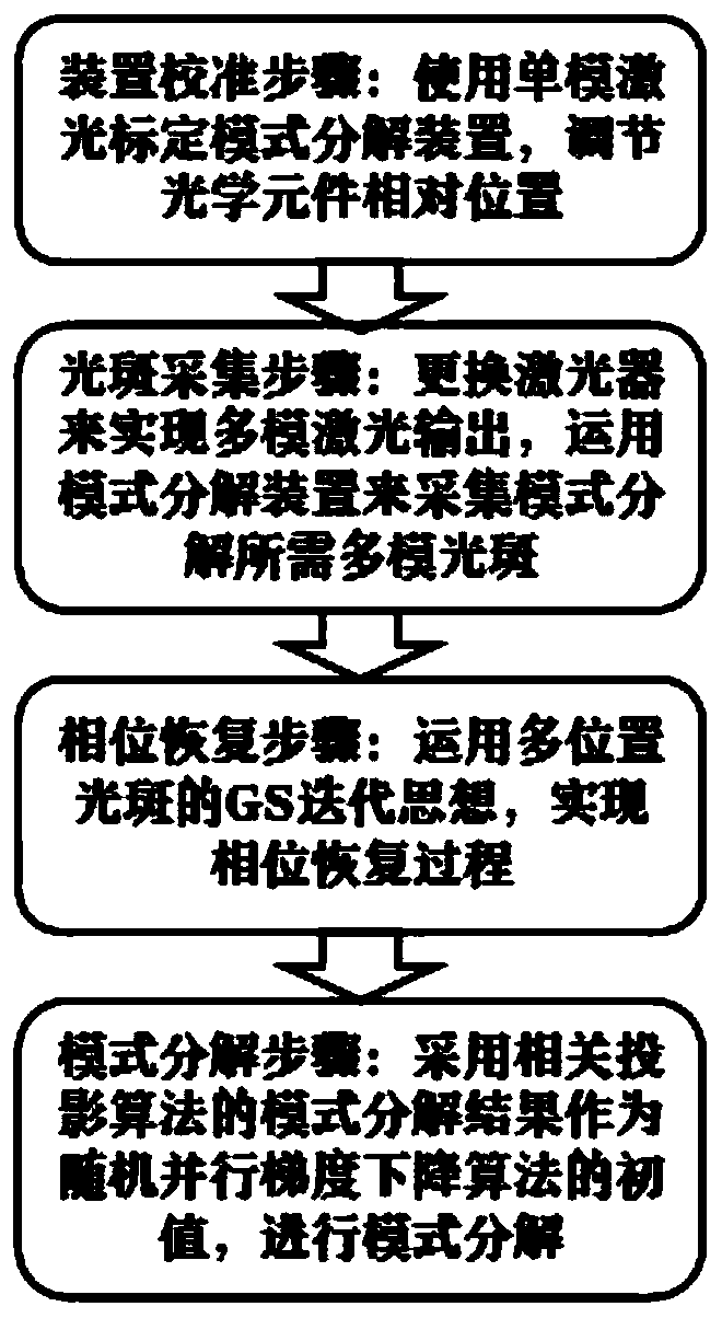
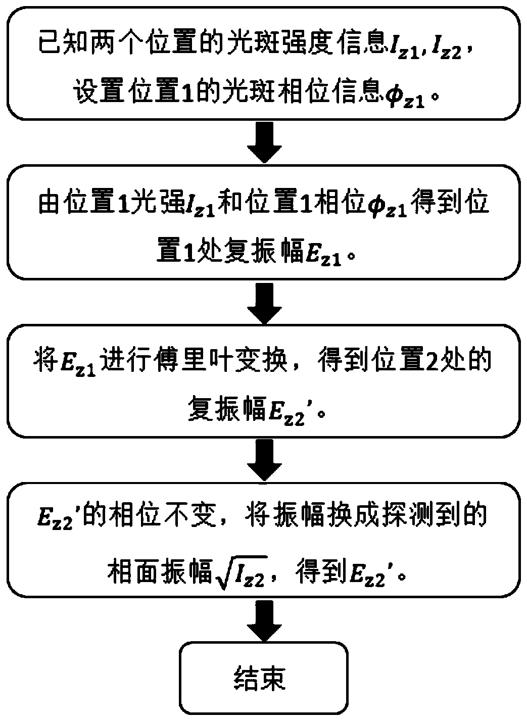
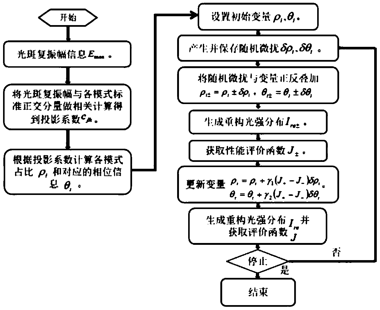
The invention discloses an optical fiber laser mode decomposition method based on phase recovery, and an implementation device thereof. The method comprises the following four steps: 1, calibrating amode decomposition device through employing a single-mode laser, and adjusting the relative position of an optical element in the mode decomposition device; 2, replacing an optical fiber laser in themode decomposition device, achieving few-mode laser output, and collecting few-mode light spots needed by mode decomposition through the mode decomposition device; 3, recovering the phase of the multimode light spot by using a GS iterative algorithm of the multi-position light spot to obtain the complex amplitude of the multimode light spot; and 4, carrying out mode decomposition on the complex amplitude by adopting a related projection algorithm, and optimizing by taking a mode decomposition result as an initial value of a random parallel gradient descent algorithm. The problem that a traditional random parallel gradient descent algorithm is prone to falling into local optimum due to sensitivity to an initial value is solved, and the number of decomposable modes is increased while the precision is kept.

Description

technical field [0001] The invention relates to the field of laser measurement, in particular to a phase recovery-based optical fiber laser mode decomposition method and an implementation device thereof. Background technique [0002] Laser technology is one of the four major inventions of the twentieth century, along with atomic energy, semiconductors and computers. For more than 40 years, laser technology based on lasers has developed rapidly and has been widely used in various fields such as industrial production, communications, information processing, medical and health, military affairs, cultural education, and scientific research, and has achieved good results. Economic and social benefits play an increasingly important role in national economic and social development. The fiber laser has the advantages of no optical lens in the resonator, no adjustment, no maintenance, and high stability, and is widely used in high-power lasers. However, mode-involved processes such...

Claims


Application Information

Patent Timeline
Patent Type & Authority Applications(China)
IPC IPC(8): G01M11/00G01J9/00G01J1/42
CPCG01M11/33G01J1/4257G01J9/00
Inventor 韩志刚李俊博朱日宏季琨皓孟令强詹涌刘一轩张晓宇
Owner NANJING UNIV OF SCI & TECH
Why Eureka
Try Eureka