A container skid-mounted compression hydrogenation device
A hydrogen refueling device and container technology, applied in the field of hydrogen refueling stations, can solve the problems of long installation and commissioning period, high land cost, and long station construction period, and achieve the effects of shortening the station construction period, small footprint, and saving station construction costs
- Summary
- Abstract
- Description
- Claims
- Application Information
AI Technical Summary
Problems solved by technology
Method used
Image
Examples
Embodiment 1
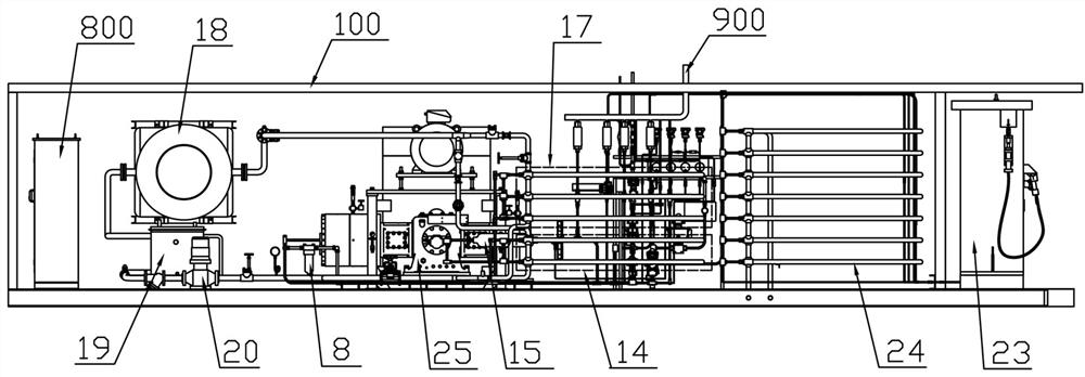
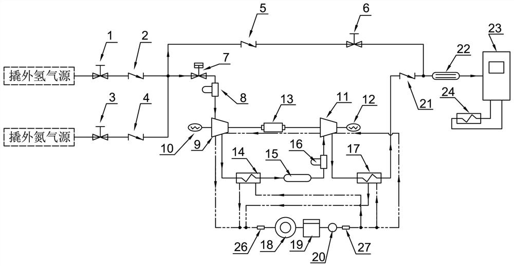
[0034] Example as figure 1 , figure 2 with Figure 15 As shown, a container skid-mounted compression hydrogenation device described in this embodiment includes: a container frame 100, the container frame 100 is composed of a top frame 101, a bottom frame 102, a front side frame 103, a rear side frame 104, a left The side frame 105 and the right side frame 106 encircle to form a rectangular parallelepiped frame structure.
[0035] Such as figure 1 , figure 2 with Figure 13 As shown, the compressor integrated frame 25 is fixedly installed in the container frame 100 and is located in the middle part of the bottom frame 102. In the compressor integrated frame 25, a motor 13, a primary compressor 9 with a leak detection device 10 and a compressor with a leak detection device 10 are fixedly arranged. The secondary compressor 11 of the leakage device 12, the motor 13 is installed in the middle part of the upper layer of the compressor integrated frame 25, the primary compress...
Embodiment 2
[0058] Embodiment 2 This embodiment is further improved on the basis of Embodiment 1, as Image 6 As shown, in this embodiment, one end of the second purge pipeline 506 is connected to the side wall of the first purge pipeline between the inlet of the first purge pipeline and the fourth check valve 5, and communicates with the first purge pipeline 505, Or one end of the second purge pipeline 506 is connected to the side wall of the main purge pipeline and communicated with the main purge pipeline 504 . The other end of the second purge pipeline 506 is connected to the side wall of the third hydrogen pipeline between the second check valve 21 and the buffer coil 22, communicated with the third hydrogen pipeline 503, or the other end of the second purge pipeline 506 is connected to On the first purge pipeline 505 between the second normally closed valve 6 and the outlet of the first purge pipeline; on the second purge pipeline 505 are provided a pressure regulator 38 and a third...
Embodiment 3
[0073] Embodiment three such as Figure 15 , Figure 16 with Figure 17 As shown, several exhaust fans are fixedly installed on the top frame 101 of the container frame 100 through corresponding exhaust fan bases 201 at intervals, and several detachable sealing plates 202 and several first fixed sealing plates 203 cover the surface of the top frame 101, A number of rolling doors 204, a number of second fixed sealing plates 205, and a number of shutters 206 cover the side frames of the four sides of the container frame 100, thereby enclosing the top surface and the four sides of the entire container frame 100, thus protecting the container frame. Each component in 100 can prevent it from being affected by external environments such as dust and rain, and can ensure its ventilation and heat dissipation performance through a number of exhaust fans and a number of louvers 206, so as to avoid the accumulation of leaked hydrogen in the container frame 100 and cause potential safety ...
PUM
 Abstract
Description
Claims
Application Information
 - R&D
- Intellectual Property
- Life Sciences
- Materials
- Tech Scout
- Unparalleled Data Quality
- Higher Quality Content
- 60% Fewer Hallucinations
Browse by: Latest US Patents, China's latest patents, Technical Efficacy Thesaurus, Application Domain, Technology Topic, Popular Technical Reports.
© 2025 PatSnap. All rights reserved.Legal|Privacy policy|Modern Slavery Act Transparency Statement|Sitemap|About US| Contact US: help@patsnap.com


