Industrial waste gas desulfurization dust removal device

A technology for desulfurization and dust removal, industrial waste gas, applied in gas treatment, use of liquid separation agent, membrane technology, etc., can solve problems such as damage to treatment equipment and inadequate waste gas desulfurization treatment, and achieve the effect of improving the degree of integration and adequacy

Pending Publication Date: 2020-08-07
易元进
View PDF11 Cites 0 Cited by
  • Summary
  • Abstract
  • Description
  • Claims
  • Application Information

AI Technical Summary

Problems solved by technology

However, it has certain defects. The desulfurization treatment of exhaust gas is not in place, and the exhaust gas is not sprayed and dust-removed at the first time. The high-temperature exhaust gas containing a lot of dust will cause great damage to the processing equipment.

Method used


Image

  • Industrial waste gas desulfurization dust removal device
  • Industrial waste gas desulfurization dust removal device
  • Industrial waste gas desulfurization dust removal device

Examples


Embodiment 1

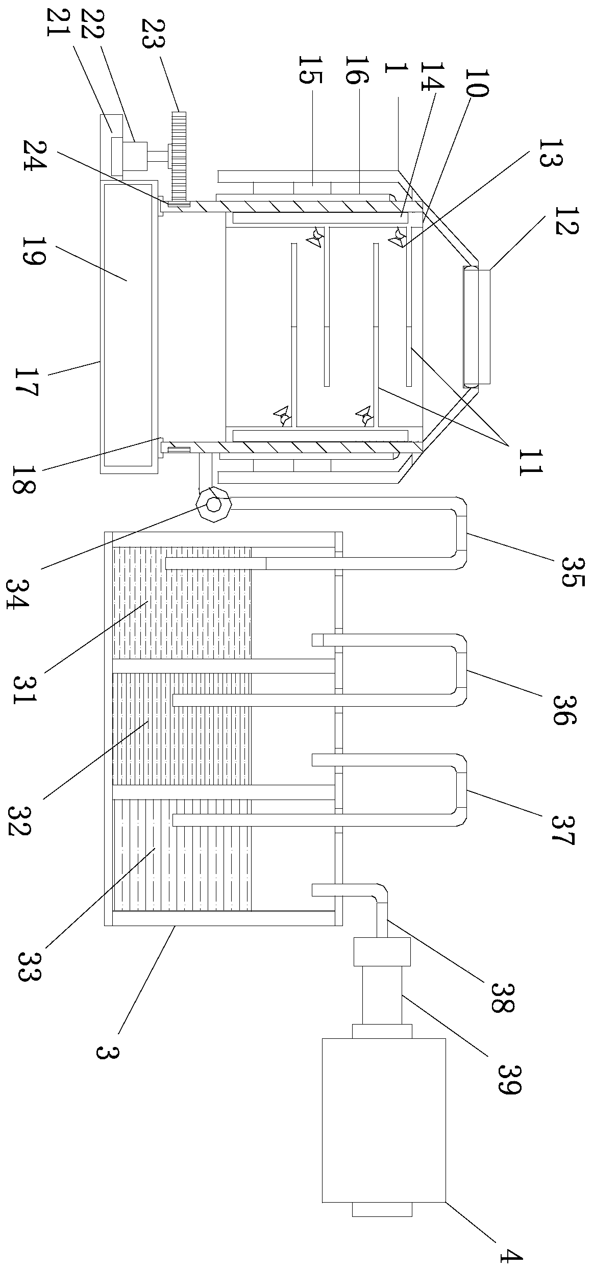
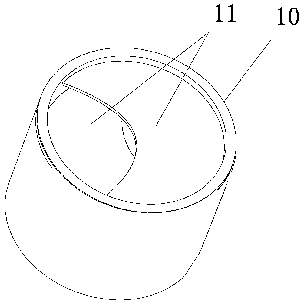
[0030] see figure 1 and figure 2 , an industrial waste gas desulfurization and dust removal device, comprising a primary purification box 1 and a secondary purification box 3, the top of the primary purification box 1 is provided with an air inlet 12, and the inner cavity of the primary purification box 1 is provided with Cooling tube 10, the cooling tube 10 is arranged at the air inlet end of the air inlet 12, the inner cavity of the cooling tube 10 is provided with several barrier plates 11, between the barrier plates 11 and the inner wall of the cooling tube 10 are An arc-shaped gap is designed, and the adjacent group of partitions 11 are arranged in a staggered shape. A shower head 13 is installed at the angle between the fixed end of the partition board 11 and the inner wall of the cooling tube 10. The outer wall of the cooling tube 10 is provided with a water storage cavity 14, and the water storage cavity 14 is connected with the shower head 13 through a conduit.

[...

Embodiment 2

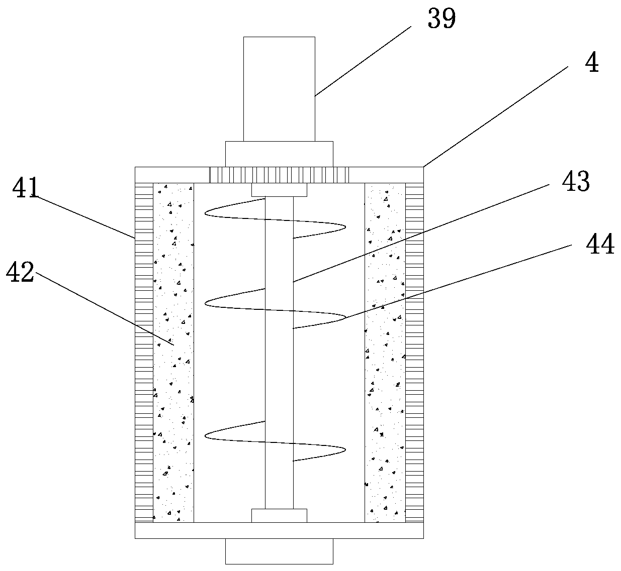
[0038] see image 3 , this embodiment is further optimized as Embodiment 1. On the basis of it, an exhaust pipe 38 is installed on the top of the lipid absorption chamber 33, and the exhaust pipe 38 is externally connected to a booster pump 39, and the booster pump The air delivery end of 39 is externally connected with an exhaust tube 4, the side wall of the exhaust tube 4 is provided with an exhaust mesh 41, and the inner wall area of ​​the exhaust tube 4 is provided with an adsorption layer 42. The inner cavity of 4 is equipped with a centerline rotating shaft 43, and a curved fan blade 44 is installed on the centerline rotating shaft 43.

[0039] Although ethanol is a non-polluting substance, in view of the high concentration of ethanol at the discharge end of the exhaust pipe 38, there is a risk of being ignited by an open flame. This application is equipped with a booster pump 39 at the exhaust to push the airflow through the adsorption layer 42 and then discharge it. ,...


PUM


Abstract

The invention relates to the technical field of industrial waste gas treatment, and specifically relates to an industrial waste gas desulfurization and dust removal device that comprises a primary purification box and a secondary purification box; a cooling cylinder is arranged in an inner cavity of the primary purification box; a plurality of baffle plates are arranged in an inner cavity of the cooling cylinder; the adjacent groups of baffle plates are arranged in a staggered manner; spraying heads are installed at the included angles between the fixed ends of the baffle plates and the innerwall of the cooling cylinder, a water storage cavity is formed in the outer wall of the cooling cylinder and connected with the spraying heads through guide pipes, and an alkaline desulfurization cavity, an acid neutralization cavity and a lipid absorption cavity are formed in an inner cavity of the secondary purification box. High-temperature waste gas is effectively subjected to cooling and heatabsorption treatment, dust and dirt in the waste gas are adhered through water liquid, and the high purification effect is achieved through multiple adsorption treatment.

Description

technical field [0001] The invention relates to the technical field of industrial waste gas treatment, in particular to an industrial waste gas desulfurization and dust removal device. Background technique [0002] Industrial waste gas refers to the general term for all kinds of pollutant gases discharged into the air during the fuel combustion and production processes in the enterprise factory area. These waste gases enter the human body through the respiratory tract through different channels, some directly cause harm, and some Accumulation will seriously endanger people's health, and different substances will have different effects. At this time, it needs to be desulfurized and dust-removed. However, the existing desulfurization and dust-removal devices are not only complicated in structure, but also have high equipment costs and short service life. Moreover, the treatment of waste gas is relatively simple and cannot achieve a wide range of applications, resulting in poor...

Claims


Application Information

Patent Timeline
Patent Type & Authority Applications(China)
IPC IPC(8): B01D47/06B01D53/78B01D53/48B01D53/42B01D53/18B01D53/04
CPCB01D47/06B01D53/04B01D53/18B01D53/42B01D53/48B01D53/78B01D2257/70
Inventor 易元进
Owner 易元进
Why Eureka
Try Eureka