
Laser cleaning device and method adopting inert gas for auxiliary cleaning

A technology of inert gas and laser cleaning, which is applied in the direction of cleaning methods and appliances, laser welding equipment, chemical instruments and methods, etc., can solve the problems of secondary damage to samples, high temperature field, etc., to improve quality, isolate operators and The effect of reaction space

Inactive Publication Date: 2020-08-07
NANCHANG HANGKONG UNIVERSITY
View PDF7 Cites 5 Cited by
  • Summary
  • Abstract
  • Description
  • Claims
  • Application Information

AI Technical Summary

Problems solved by technology

However, because the working principle of laser cleaning is to apply a high-energy laser beam to the surface of the sample, an ultra-high temperature field will be generated, which will contribute to the secondary oxidation of the metal and cause secondary damage to the sample.

Method used


Image

  • Laser cleaning device and method adopting inert gas for auxiliary cleaning
  • Laser cleaning device and method adopting inert gas for auxiliary cleaning
  • Laser cleaning device and method adopting inert gas for auxiliary cleaning

Examples


Embodiment 1

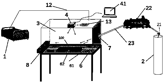
[0026] Optionally attached with a thickness of 1mmAl 2 o 3 The double-layer material of 2024 aluminum alloy with an oxide layer of 5cm×5cm×1cm is the sample 100 to be cleaned. Argon gas (ie inert gas) is used, and a layer of high-temperature-resistant glass fiber is placed outside the waste collection box. Al 2 o 3 The oxide layer is cleaned.

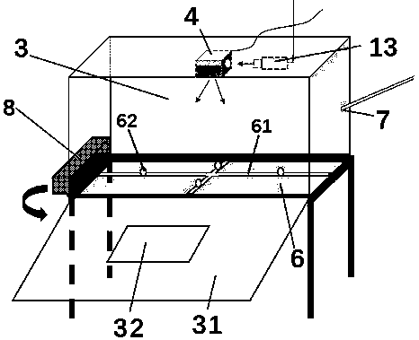
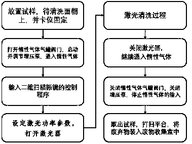
[0027] The first step: first place the sample 100 to be cleaned on the center of the platform 6, and place the Al 2 o 3 The cleaning surface is facing upwards, and the four sides of the sample 100 to be cleaned are fastened by clamps 62 for fixing.

[0028] Step 2: Open the valve 21 at the outlet of the inert gas tank 2, start the booster pump 22, set the output pressure to about 15MPa, and make the inert gas output continuously for 5mins. At the same time, observe whether the sample 100 to be cleaned is loose. Adjust the holding state of the sample to be cleaned until the sample to be cleaned is stable and firm under the impact o...

Embodiment 2

[0035] Select a 7075 aluminum alloy substrate of 10cm×10cm×2cm, and apply a 100μm acrylic polyurethane paint layer on the upper layer, use argon gas (that is, inert gas), and cover the outside of the waste collection box with a layer of high-temperature-resistant glass fiber. Clean the acrylic polyurethane paint layer of the object to be cleaned.

[0036] Among them: the third step is to set the laser output power of the laser host 1 as 500W, input and control the laser scanning parameters in the computer 41, the spot diameter is 0.5mm, the scanning speed is 2500mm / s, and the spot overlap rate is 50%. In the fourth step, the cleaning time is 16s. Others are the same as in Example 1.


PUM


Abstract

The invention discloses a laser cleaning device and method adopting inert gas for auxiliary cleaning. The method comprises the steps that a clamp fixes a sample to be cleaned; a booster pump is started, the insert gas is delivered into a closed cleaning box through a pipeline, and the insert gas is continuously introduced; the moving state of a two-dimensional scanning galvanometer is controlled;laser cleaning is carried out; and after the inert gas is continuously introduced for 15 minutes, the sample to be cleaned is taken out, and laser cleaning is completed. According to the laser cleaning device, through mutual cooperation of an inert gas control device, a laser and a two-dimensional scanning device, parameters such as the laser spot size and laser scanning speed can be adjusted to control the output time and impact force of the inert gas, so that the sample is prevented from being oxidized again in the high-temperature process of laser cleaning, and the more pure sample is obtained; the laser cleaning quality and effect are improved; and the sealed cleaning box is arranged, so that an operator and the reaction space can be well isolated, and the requirement of safe operationis met.

Description

technical field [0001] The invention relates to the technical field of laser cleaning, in particular to a device and method for assisting laser cleaning with inert gas. Background technique [0002] Traditional cleaning methods include chemical reagent removal method, manual grinding method and shot blasting paint removal method. In our country, the requirements of environmental protection laws and regulations are becoming more and more stringent, and people's awareness of environmental protection and safety is getting stronger and stronger. These three methods will more or less cause environmental pollution. In traditional cleaning methods, parts need to be disassembled, which is inefficient. Relatively speaking, laser cleaning technology can well overcome the above shortcomings in the process of cleaning samples. Laser cleaning is usually to effectively clean the pollutants on the surface of the substrate without damaging the substrate, and adapt to various cleaning obje...

Claims


Application Information

Patent Timeline
IPC IPC(8): B08B7/00B08B13/00B23K26/12
CPCB08B7/0042B08B13/00B23K26/123
Inventor 李多生王凯叶寅王明娣左敦稳冯庆晓王国波
Owner NANCHANG HANGKONG UNIVERSITY
Learn More