Eureka AIR delivers breakthrough ideas for toughest innovation challenges, trusted by R&D personnel around the world.

Plastic film blowing system with reheating function

A membrane system and plastic technology, used in household appliances, other household appliances, flat products, etc., can solve the problems of low energy utilization rate, environmental pollution, physical injury of operators, etc., to improve energy utilization rate and compact structure. , the effect of reducing emissions

Inactive Publication Date: 2020-08-07
明柏森
View PDF9 Cites 3 Cited by
  • Summary
  • Abstract
  • Description
  • Claims
  • Application Information

AI Technical Summary

Problems solved by technology

The existing raw material drying devices basically use one of static or dynamic drying, and the hot air is directly discharged as exhaust gas after being used only once, and the energy utilization rate is low; at the same time, the current film blowing device produces The exhaust gas is directly discharged into the atmosphere, which is easy to cause harm to the operator's body and pollute the environment

Method used


Image

  • Plastic film blowing system with reheating function
  • Plastic film blowing system with reheating function
  • Plastic film blowing system with reheating function

Examples


Embodiment Construction

[0038] The preferred embodiments of the present invention will be described below in conjunction with the accompanying drawings. It should be understood that the preferred embodiments described here are only used to illustrate and explain the present invention, and are not intended to limit the present invention.

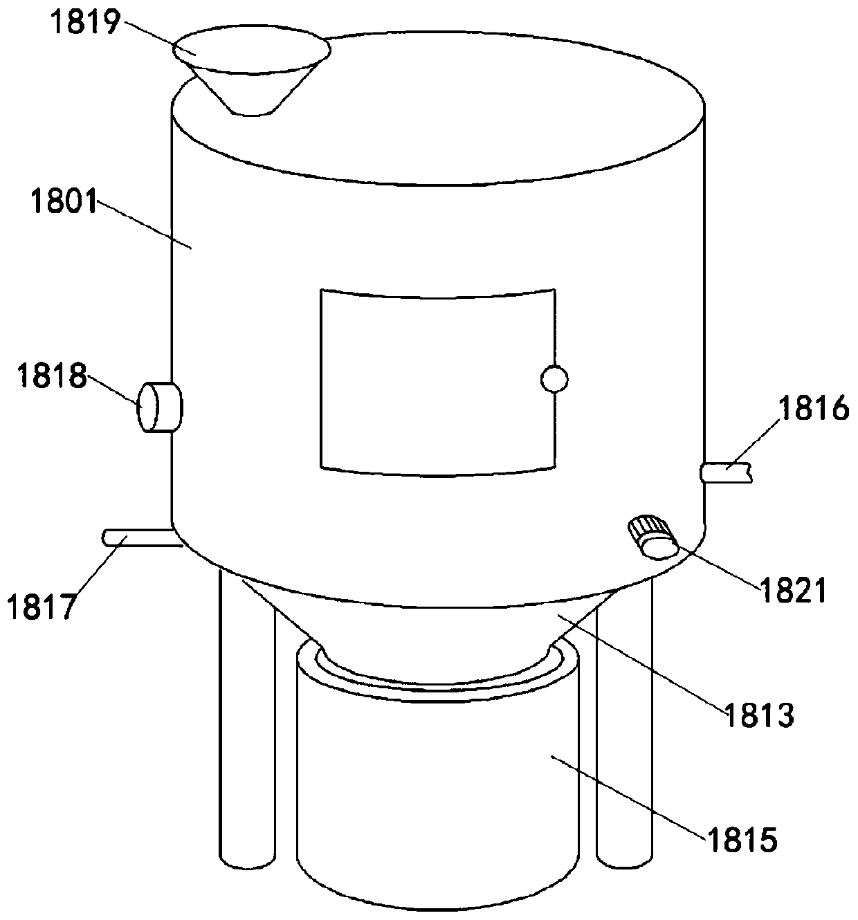
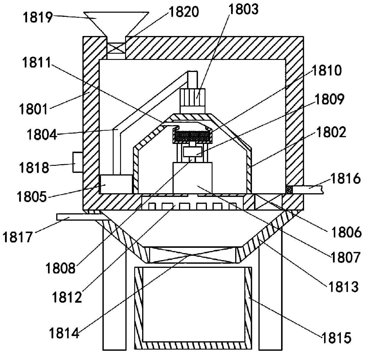
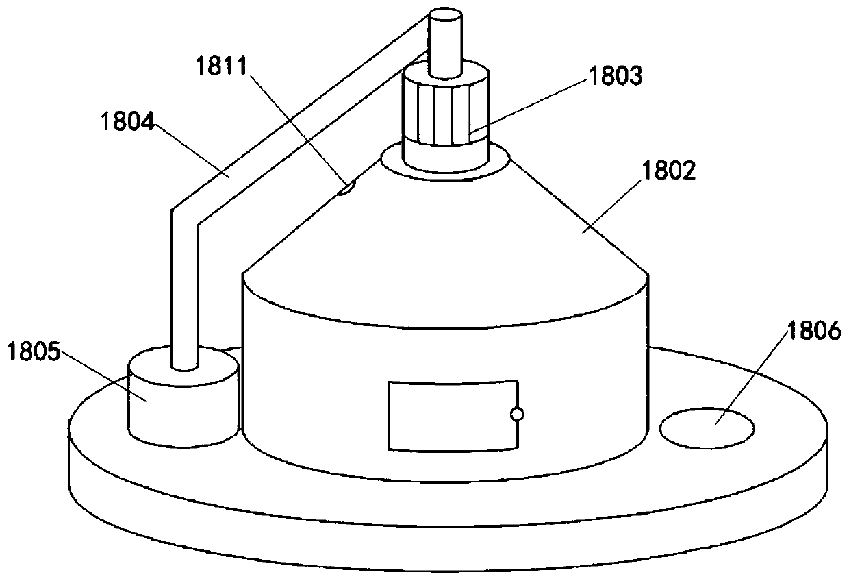
[0039] Example: such as Figure 1-14A plastic film blowing system with a reheating function is shown, including a raw material drying device and a film blowing device, and the plastic raw materials dried by the raw material drying device are manually fed into the storage hopper 7 of the film blowing device; the raw material drying device includes drying Housing 1801, the bottom wall of the drying housing 1801 is fixed with a reheat cylinder 1802, the upper end of the reheat cylinder 1802 is fixed with a stirring motor 1803, the output shaft of the stirring motor 1803 is fixed with a stirring block 1805 through a folding rod 1804, and the drying An electric blanking ...


PUM


Abstract

The invention discloses a plastic film blowing system with a reheating function. The plastic film blowing system involves a raw material drying device and a film blowing device, wherein plastic raw material dried by the raw material drying device is manually fed into a storage hopper of the film blowing device; the raw material drying device comprises a drying housing, wherein the bottom wall of the drying housing is fixedly connected with a reheating cylinder, a stirring motor is fixedly connected to the upper end of the reheating cylinder, and an output shaft of the stirring motor is fixedlyconnected with a stirring block through a folding rod; an electric material falling door is formed in the bottom wall of the drying housing, an electric heater is fixedly connected in the reheating cylinder, the upper end of the electric heater is in communication with an outlet of a suction fan through an air inlet pipe of the heater, an inlet of the suction fan is in communication with an outlet of an activated carbon box, multiple layers of honeycomb activated carbon layers are arranged in the activated carbon box, an inlet air pipe of the activated carbon box is provided with an opening located at the surface of the reheating cylinder, and an outlet pipe of the electric heater is in communication with a plurality of branched spray pipes; and a material falling housing is arranged below the drying housing, a gate plate door is arranged at the bottom of the material falling housing, and a material collecting barrel with an opening in the upper end is placed below the gate plate door.

Description

technical field [0001] The invention relates to the technical field of film blowing equipment, in particular to a plastic film blowing system with reheating function. Background technique [0002] The film blowing machine is a kind of film production automation equipment. The film blowing machine mainly heats and melts the plastic particles and then blows them into a film. Expanding herringbone board, traction roller, coiling to roll the finished film into a tube, suitable for blowing low-density polyethylene, high-density polyethylene and linear low-density plastic films, widely used in fruit, food, clothing, textiles, Internal and external packaging of civil and industrial products such as strain cultivation and daily necessities; [0003] Before the plastic raw material is melted, it needs to be dried by hot air to ensure the effect of melting. The existing raw material drying devices basically use one of static or dynamic drying, and the hot air is directly discharged ...

Claims


Application Information

Patent Timeline
Patent Type & Authority Applications(China)
IPC IPC(8): B29B13/06B29C48/10B29C48/27B29C48/25B29C48/00B29C55/28B29L7/00
CPCB29B13/065B29L2007/00B29C48/0017B29C48/10B29C48/25B29C48/27
Inventor 明柏森
Owner 明柏森
Why Eureka
Eureka Blog
Learn More