
Pulse train type repetition frequency-adjustable laser ranging method

A repetition rate, laser ranging technology, applied in measurement devices, re-radiation of electromagnetic waves, radio wave measurement systems, etc., can solve the problem of single-photon detector damage, short distance, and increased backscattered light. Satellite laser echo detection difficulty, etc.

Active Publication Date: 2020-08-07
SHANGHAI ASTRONOMICAL OBSERVATORY CHINESE ACAD OF SCI
View PDF7 Cites 1 Cited by
  • Summary
  • Abstract
  • Description
  • Claims
  • Application Information

AI Technical Summary

Problems solved by technology

Ultra-high repetition rate satellite laser ranging, the distance between pulses is short, the distance of laser transmission in the atmosphere is greater than 3km, and the corresponding time of the distance of backscattered light is greater than 10us, that is, within 10us there are lasers transmitted from the atmosphere after the laser The scattered light reaches the telescope. After the laser emits a pulse, when the next pulse is emitted, the backscattered photons of the previous pulse have reached the receiving telescope. Undoubtedly, the backscattered light increases the difficulty of detecting the satellite laser echo; After the launch, due to the backscattered light transmitted by the laser in the atmosphere, a large amount of laser backscattered light will be received by the receiving telescope to the single photon detector. If the single photon detector is turned on at this time, the single photon detector will be very slow. It is easy to achieve response saturation and easily cause damage to single photon detectors, which limits the development of satellite laser ranging to higher repetition rates

Method used


Image

  • Pulse train type repetition frequency-adjustable laser ranging method
  • Pulse train type repetition frequency-adjustable laser ranging method
  • Pulse train type repetition frequency-adjustable laser ranging method

Examples


Embodiment Construction

[0022] The present invention will be described in further detail below through specific embodiments and in conjunction with the accompanying drawings.

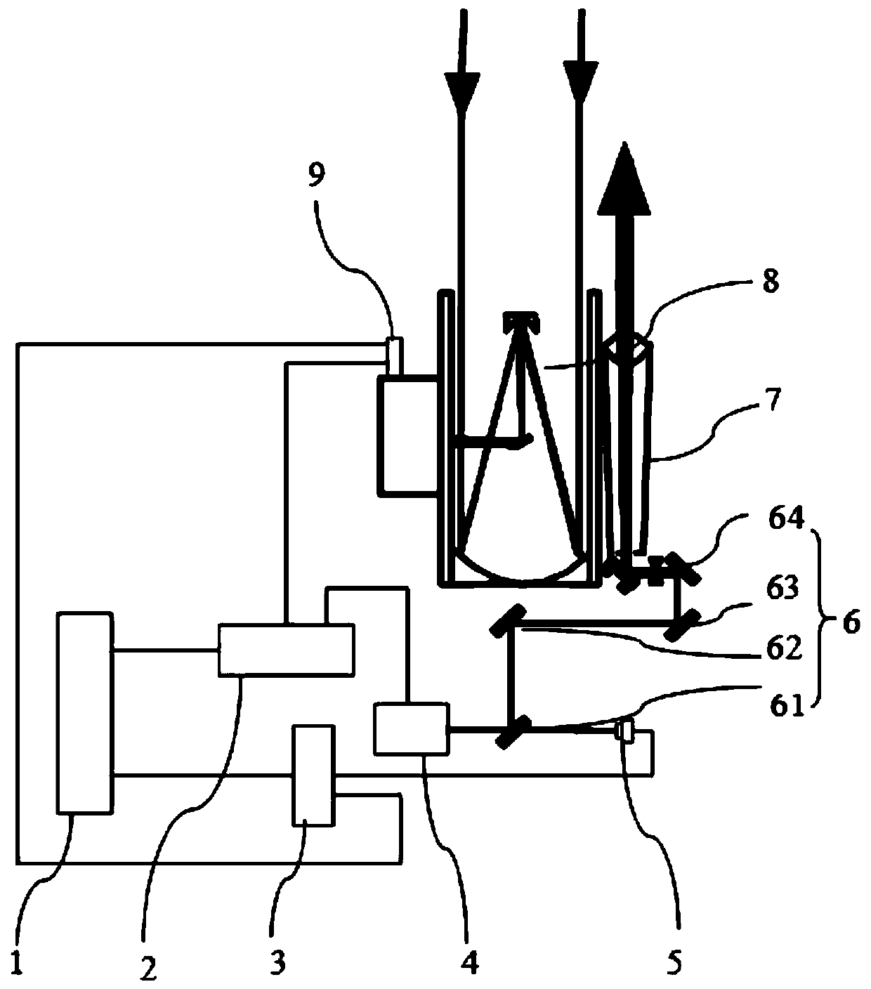
[0023] Such as figure 1 Shown is a pulse group repetition frequency adjustable laser ranging method according to an embodiment of the present invention, including a computer terminal 1, a range gate controller 2, an event timer 3, a laser 4, and a photodetector 5, Mirror group 6, transmitting telescope 7, receiving telescope 8, single photon detector 9.

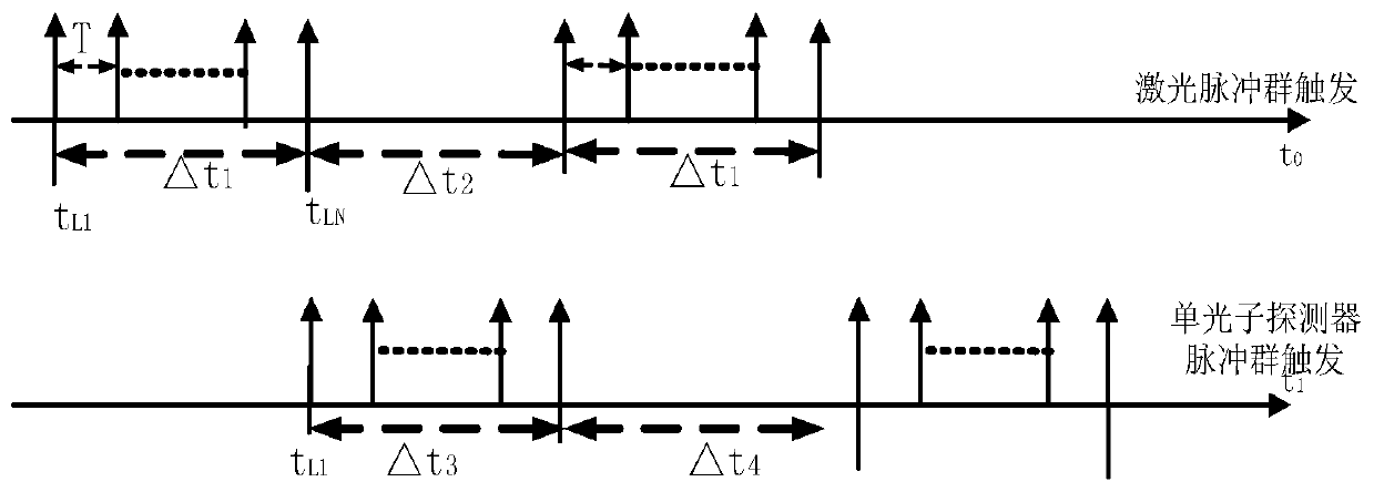
[0024] The laser pulse group and the gate control pulse group are input by the computer terminal 1 according to the orbit distance of the target satellite, and the orbit distance prediction value is input to the range gate controller 2, and the ignition pulse group signal is first output to the laser 4, and the group contains hundreds of trigger pulses , the laser 4 corresponds to the output laser pulse group, which is transmitted by the reflector group 6, and is emitted by ...


PUM


Abstract

The invention discloses a pulse train type repetition frequency-adjustable laser ranging method. A computer terminal, a distance gate controller, an event timer, a laser, a photoelectric detector, a reflector group, a transmitting telescope, a receiving telescope and a single-photon detector are adopted. The computer terminal outputs a satellite distance forecast value to the distance gate controller; an ignition pulse train triggers the laser to output a laser pulse train; hundreds of pulses exist in the laser pulse train; part of the light is detected by the photoelectric detector, and the other light is transmitted to a satellite through the reflector group and the transmitting telescope; laser pulse train echoes returned by the satellite are received by the receiving telescope, and atthis moment, the distance gate controller outputs gate control pulse train signals to trigger the single-photon detector to receive the laser echoes; the event timer records the moment; and satellitedistance measurement is achieved through the processing of the computer terminal. By controlling the number of the pulses in the pulse train and the frequency period of the pulse train, adjustable ultrahigh repetition frequency satellite laser ranging can be achieved, and the development and application of laser ranging are promoted.

Description

technical field [0001] The invention relates to the field of laser ranging, in particular to a laser ranging method with adjustable pulse group repetition frequency. Background technique [0002] Satellite laser ranging accurately measures the round-trip time interval of the laser pulse from the ground observation point to the satellite reflector, thereby calculating the precise distance between the satellite and the site. At present, the ranging accuracy reaches sub-centimeters and millimeters, and it is the most important technology in satellite orbit measurement technology. A technology with the highest precision, it is widely used in scientific research in the fields of precise orbit determination of space objects, parameters of the earth's gravity field, verification of relativity, high-precision time comparison, etc. The breakthrough of major national special projects such as detection provides indispensable high-precision measurement data support. [0003] With the c...

Claims


Application Information

Patent Timeline
IPC IPC(8): G01S17/10
CPCG01S17/10
Inventor 龙明亮张海峰邓华荣程志恩吴志波张忠萍
Owner SHANGHAI ASTRONOMICAL OBSERVATORY CHINESE ACAD OF SCI
Learn More