
A reinforced anti-rotation expanded beam optical fiber contact

A technology of beam expanding optical fiber and contacts, which is applied in the field of beam expanding optical fiber contacts, can solve the problems that the light spot becomes very sensitive to the axis angle, the repeatability of the test results is poor, and the quality of the optical core number transmission is affected, so as to improve the repeatability The effect of avoiding axis deviation and insertion loss and improving work reliability

Active Publication Date: 2022-02-08
SHANGHAI AEROSPACE SCI & IND ELECTRIC APPLIANCE RES INST
View PDF8 Cites 0 Cited by
  • Summary
  • Abstract
  • Description
  • Claims
  • Application Information

AI Technical Summary

Problems solved by technology

According to the relevant technical data and experimental tests, the expanded beam optical fiber contact can effectively increase the diameter of the spot and greatly reduce the impact of dust on product performance, but at the same time it brings an adverse effect, that is, the beam has been expanded, and the spot has no effect on the product. Axis angle can become very sensitive
When the expanded beam optical fiber contact in the prior art is used in the connector, the outer ferrule is docked with the ceramic sleeve. When the tail end optical cable is heavy or the hole position of the connector for installing the expanded beam optical fiber contact is deviated, the outer ferrule is completely relied on. The matching alignment of the core and the ceramic sleeve prevents the skew of the axis between the beam expansion fiber ferrule and the beam expansion fiber jack, and the ceramic sleeve is a thin-walled ceramic piece with grooves, which has poor bending resistance. It will break when it is subjected to a large bending stress. Even if the ceramic sleeve is not broken, the axis angle deviation between the beam expanding fiber ferrule and the beam expanding fiber jack will increase the insertion loss and affect the optical core number. On the other hand, due to the limitation of processing technology, there is always a certain ellipticity error in the radial direction of the parts processing of the expanded beam optical fiber contact, which causes the assembled expanded beam optical fiber contact to be tested separately and loaded into the connector. Due to the inconsistency of the radial angle of the butt joint during the post-test, there are differences in the insertion loss and other indicators, and the repeat consistency of the test results is poor

Method used


Image

  • A reinforced anti-rotation expanded beam optical fiber contact
  • A reinforced anti-rotation expanded beam optical fiber contact
  • A reinforced anti-rotation expanded beam optical fiber contact

Examples


Embodiment Construction

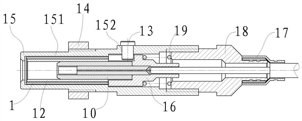
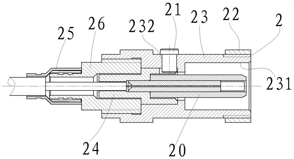
[0034] refer to figure 1 , the present invention includes an optical fiber ferrule 1 and an optical fiber jack 2;

[0035] refer to figure 1 , figure 2 , the optical fiber ferrule 1 is composed of a first beam expanding ferrule 10, a protective tube 11, a ceramic sleeve 12, a first anti-rotation pin 13, a first nut 14, a needle housing 15, a needle tail handle 16, a first press Sleeve 17, needle sleeve 18 and spring 19 constitute;

[0036] The needle housing 15 is a cylindrical member with a stepped hole and an internal thread inside, and an external thread and a guide column 151 outside, and a first pin hole 152 is provided on the wall of the cylinder.

[0037] refer to figure 1 , figure 2 , Figure 4 , the needle tail handle 16 is a cylindrical member with a stepped hole inside and a spring seat outside, and a first keyway 161 is provided on the wall of the cylinder.

[0038] refer to figure 1 , figure 2 , the needle sleeve 18 is a cylindrical member with an exte...


PUM


Abstract

The invention discloses a reinforced anti-rotation expanded beam optical fiber contact piece, which includes an optical fiber ferrule and an optical fiber jack; The guide hole is set on the body, when the optical fiber ferrule is inserted into the optical fiber jack, the guide column of the needle housing first contacts with the guide hole of the hole housing, inserts and guides, ensuring the connection between the optical fiber ferrule and the optical fiber jack The coaxiality avoids the deviation of the axis and the insertion loss when the optical path of the first beam expanding ferrule is connected with the second beam expanding ferrule, and ensures the transmission quality of the optical signal; the present invention adopts the first pin hole and the A first anti-rotation pin is set between the first key grooves of the needle tail handle, and a second anti-rotation pin is set between the second pin hole of the hole housing and the second key groove of the hole tail handle, through the anti-rotation pin and the plug housing And the positioning of the socket housing ensures that the radial angles of the first beam expander ferrule and the second beam expander ferrule are consistent when the optical paths are docked, thereby improving the repeatability of test results.

Description

technical field [0001] The invention relates to the technical field of optical fiber connectors, in particular to a reinforced anti-rotation expanded beam optical fiber contact piece. Background technique [0002] As the related technologies of expanded beam optical fiber contacts become more and more mature, they are used more and more in connectors. According to the relevant technical data and experimental tests, the expanded beam optical fiber contact can effectively increase the diameter of the spot and greatly reduce the impact of dust on product performance, but at the same time it brings an adverse effect, that is, the beam has been expanded, and the spot has no effect on the product. Axis angle can become very sensitive. When the expanded beam optical fiber contact in the prior art is used in the connector, the outer ferrule is docked with the ceramic sleeve. When the tail end optical cable is heavy or the hole position of the connector for installing the expanded b...

Claims


Application Information

Patent Timeline
Patent Type & Authority Patents(China)
IPC IPC(8): G02B6/38
CPCG02B6/389G02B6/3821
Inventor 卢贵斌
Owner SHANGHAI AEROSPACE SCI & IND ELECTRIC APPLIANCE RES INST
Learn More