Method and system for positioning mark center with weak contrast

A positioning mark and contrast technology, which is applied in image data processing, instrumentation, calculation, etc., can solve the problems of weak contrast positioning mark center, limitation and low precision, and achieves the effects of reliable results, good stability and fast speed.

Pending Publication Date: 2020-08-07
ZHAOQING ZHONGDAO OPTOELECTRONICS EQUIP CORP
1 Cites 1 Cited by

AI-Extracted Technical Summary

Problems solved by technology

[0004] Based on the limitations and low precision of the current method, the presen...

Abstract

The invention discloses a method and a system for positioning a mark center with weak contrast. The method comprises the following steps: performing edge extraction on a red component of an image to obtain an edge image, performing Gaussian filtering and binarization on the edge image to obtain a binarized image, performing dilation operation on the binarized image and removing noise to obtain a denoised image, and finally calculating a weak contrast positioning mark center. The method has the characteristics of high precision, high speed and good stability in a visual detection system. The precision of the method reaches the sub-pixel level, the result is reliable, and the method is widely applied to the visual inspection industry; and the method and system suitable for similar images with symmetry and weak contrast.

Application Domain

Image enhancementImage analysis

Technology Topic

Computer graphics (images)Pattern recognition +6

Image

  • Method and system for positioning mark center with weak contrast
  • Method and system for positioning mark center with weak contrast
  • Method and system for positioning mark center with weak contrast

Examples

  • Experimental program(4)

Example Embodiment

[0038] Example 1
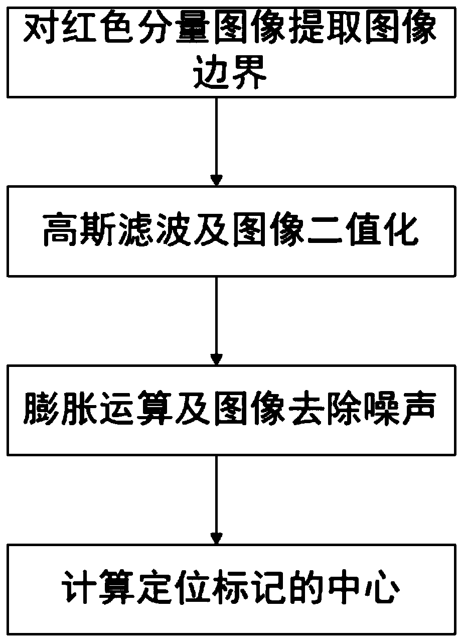
[0039] Such as figure 1 As shown, the object of the present invention is to obtain the center of a weak contrast positioning mark. The calculation process is as follows:
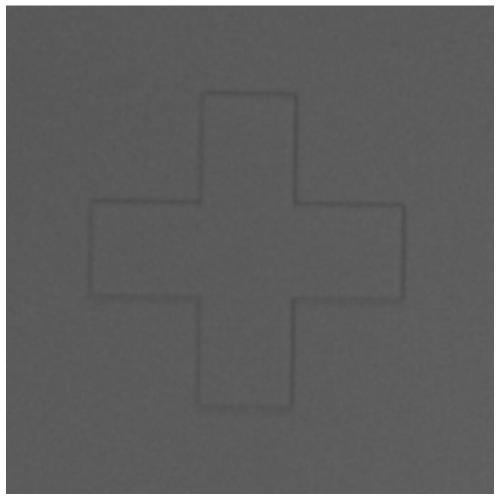
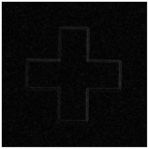
[0040] 1. Extract the image with the red component image of the positioning marker image (such as figure 2 The image shown) has the boundary as image 3 :
[0041] A) Obtain the red component of the image and calculate it according to the ratio of the RGB component of the image. The ratio of the RGB component is 0.299, 0.587, 0.114.
[0042] B) Extract the edge of the positioning mark image using a 3X3 Sobel filter, the horizontal and vertical filters are as follows:
[0043]
[0044] 2. Gaussian filtering and image binarization such as Figure 4 :
[0045] A) Gaussian filtering uses a 3X3 kernel, and the filter is as follows:
[0046]
[0047] B) Calculate the threshold of image binarization. First calculate the grayscale histogram of the image, filter the high-frequency signal in a certain proportion according to the image area, and record the grayscale value M of the corresponding histogram at this time when the set area is reached. Then the average value N of the image is calculated, and the average value of the grayscale value M and the average value N is used as the final threshold for binarization, and finally the image is binarized.
[0048] 3. Image expansion operation and noise removal such as Figure 5 :
[0049] A) Perform expansion processing on the binary image;
[0050] B) Remove noise, calculate the run-length code of the binary image, set the merge radius to 2 pixels, and calculate the gathering feature of the merged area. For each clustered area whose width and height are less than 30 pixels, it is judged as a noise point, and the gray scale of the pixel points in the area is set to 0.
[0051] 4. The method of calculating the center of the positioning mark image is as follows Image 6 :
[0052] A) Count the number of pixels with a gray level of 255 in a binary image according to the row. Arrange the number of pixels with a gray level of 255 in each row in ascending order, and obtain the maximum number of pixels with a gray level of 255. If the number of pixels exceeds 60% of the maximum value, the row coordinates are retained, and the average value of the retained row coordinates is calculated. The average value is the vertical coordinate of the center of the positioning mark image.
[0053] B) Count the number of pixels with a gray level of 255 in a binary image according to the column, arrange the number of pixels in each column with a gray level of 255 in descending order, and obtain the maximum number of gray levels of these columns as 255 pixels. If the number of pixels exceeds 60% of the maximum value, the column coordinates are retained, and the retained column coordinates are averaged. The average value is the horizontal coordinate of the center of the positioning mark image.
[0054] The beneficial effect of this embodiment is that the boundary extraction of the positioning marker image is achieved by extracting the red component image, after Gaussian filtering and binarization, the image expansion operation removes the noise points again, and finally the average coordinates of the boundary points are used to obtain the center position of the positioning marker, and the accuracy is sub-optimal. The results are relatively reliable, and are widely used in the visual inspection industry; the present invention is applicable to similar images with symmetry and weak contrast.

Example Embodiment

[0055] Example 2
[0056] This embodiment provides a system for locating the center of a mark with weak contrast, such as Figure 7 Shown, including:
[0057] The image boundary extraction module 100 is used for the extracted red component image to find the boundary of the positioning mark image;
[0058] The image binarization module 200 is used to binarize the image after Gaussian noise is removed;
[0059] The image denoising module 300 is used to remove sparse discrete points and retain useful information about the edge of the positioning mark image;
[0060] The center module 400 for calculating the positioning mark image is used to calculate the horizontal and vertical coordinates of the center of the positioning mark image.
[0061] The beneficial effect of this embodiment is that the boundary extraction of the positioning marker image is achieved by extracting the red component image, after Gaussian filtering and binarization, the image expansion operation removes the noise points again, and finally the average coordinates of the boundary points are used to obtain the center position of the positioning marker, and the accuracy is sub-optimal. The results are relatively reliable, and are widely used in the visual inspection industry; the present invention is applicable to similar images with symmetry and weak contrast.

Example Embodiment

[0062] Example 3
[0063] This embodiment provides an electronic device that includes a memory, a processor, and a computer program stored on the memory and capable of running on the memory, and the processor executes the program to implement the method as described in Embodiment 1. The method of locating the center of the mark with weak contrast is described.

PUM

no PUM

Description & Claims & Application Information

We can also present the details of the Description, Claims and Application information to help users get a comprehensive understanding of the technical details of the patent, such as background art, summary of invention, brief description of drawings, description of embodiments, and other original content. On the other hand, users can also determine the specific scope of protection of the technology through the list of claims; as well as understand the changes in the life cycle of the technology with the presentation of the patent timeline. Login to view more.

Similar technology patents

Network and mobile terminal water quality detection method and detection system

PendingCN112161980Areliable resultsdata available
Owner:刘邦楠

Gel temperature testing method for polyvinyl chloride paste resin

PendingCN112362532Aeasy to operatereliable results
Owner:SHENYANG CHEM IND CO LTD

Classification and recommendation of technical efficacy words

  • reliable results
  • High precision

In-vitro pollen germination liquid medium of balloon flower and method using same to determine pollen viability thereof

InactiveCN101633902AEasy to observe and measurereliable results
Owner:SHANGLUO UNIV

Method for testing and identifying cepaea hortensis through polymerase chain reaction (PCR)

ActiveCN102952885Areliable resultsStrong specificity
Owner:INSPECTION & QUARANTINE TECH CENT OF FUJIAN ENTRY EXIT INSPECTION & QUARANTINE BUREAU

Application of miR-126-3p to porcine ovarian granular cells

ActiveCN105567686Areliable results
Owner:SOUTH CHINA AGRI UNIV

Rapid identification method for atrazine residual phytotoxicity and application thereof

InactiveCN105044058ASimple and efficient operationreliable results
Owner:PLANT PROTECTION RES INST OF GUANGDONG ACADEMY OF AGRI SCI

Pathogenic bacteria immune detection chip and preparation method thereof

InactiveCN1603832Areliable resultsThe result saves time and effort
Owner:SOUTHEAST UNIV

Method for forecasting short-term power in wind power station

InactiveCN102102626AHigh precision
Owner:NORTH CHINA ELECTRIC POWER UNIV (BAODING) +1

Numerical control machine tool wear monitoring method

InactiveCN102091972AHigh precisionReal-time monitoring of tool wear
Owner:HUAZHONG UNIV OF SCI & TECH +1

Advertisement recommendation method and apparatus

ActiveCN104965890AHigh precisionPrecise screening
Owner:SHENZHEN TENCENT COMP SYST CO LTD
Why Eureka
Try Eureka