
Stator core cooling structure and motor cooling system

A stator core and cooling structure technology, applied in the direction of cooling/ventilation device, magnetic circuit shape/style/structure, winding conductor shape/style/structure, etc., can solve high manufacturing cost, long processing cycle and cumbersome assembly process and other problems, to achieve the effect of solving long processing cycle, high cooling efficiency and compact structure

Pending Publication Date: 2020-08-07
JING JIN ELECTRIC TECHNOLOGIES (BEIJING) CO LTD
View PDF0 Cites 13 Cited by
  • Summary
  • Abstract
  • Description
  • Claims
  • Application Information

AI Technical Summary

Problems solved by technology

[0003] The existing way to cool the inside of the motor is to slot the inner wall of the motor housing to set up a cooling oil circuit. Long processing cycle, high manufacturing cost, cumbersome assembly process and other issues

Method used


Image

  • Stator core cooling structure and motor cooling system
  • Stator core cooling structure and motor cooling system
  • Stator core cooling structure and motor cooling system

Examples


Embodiment 1

[0040] The embodiment of the invention discloses a stator core cooling structure, which includes a stator core 1 and a motor housing 2 .

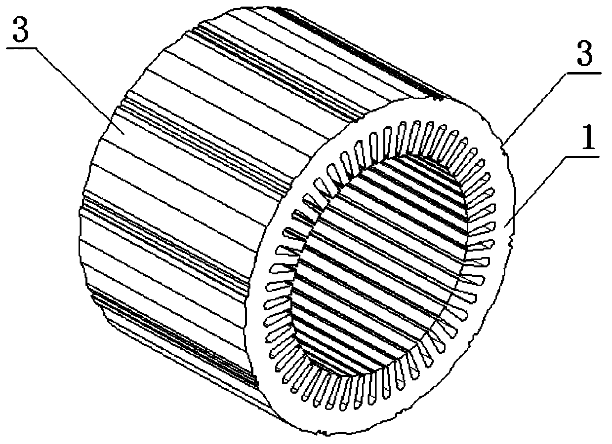
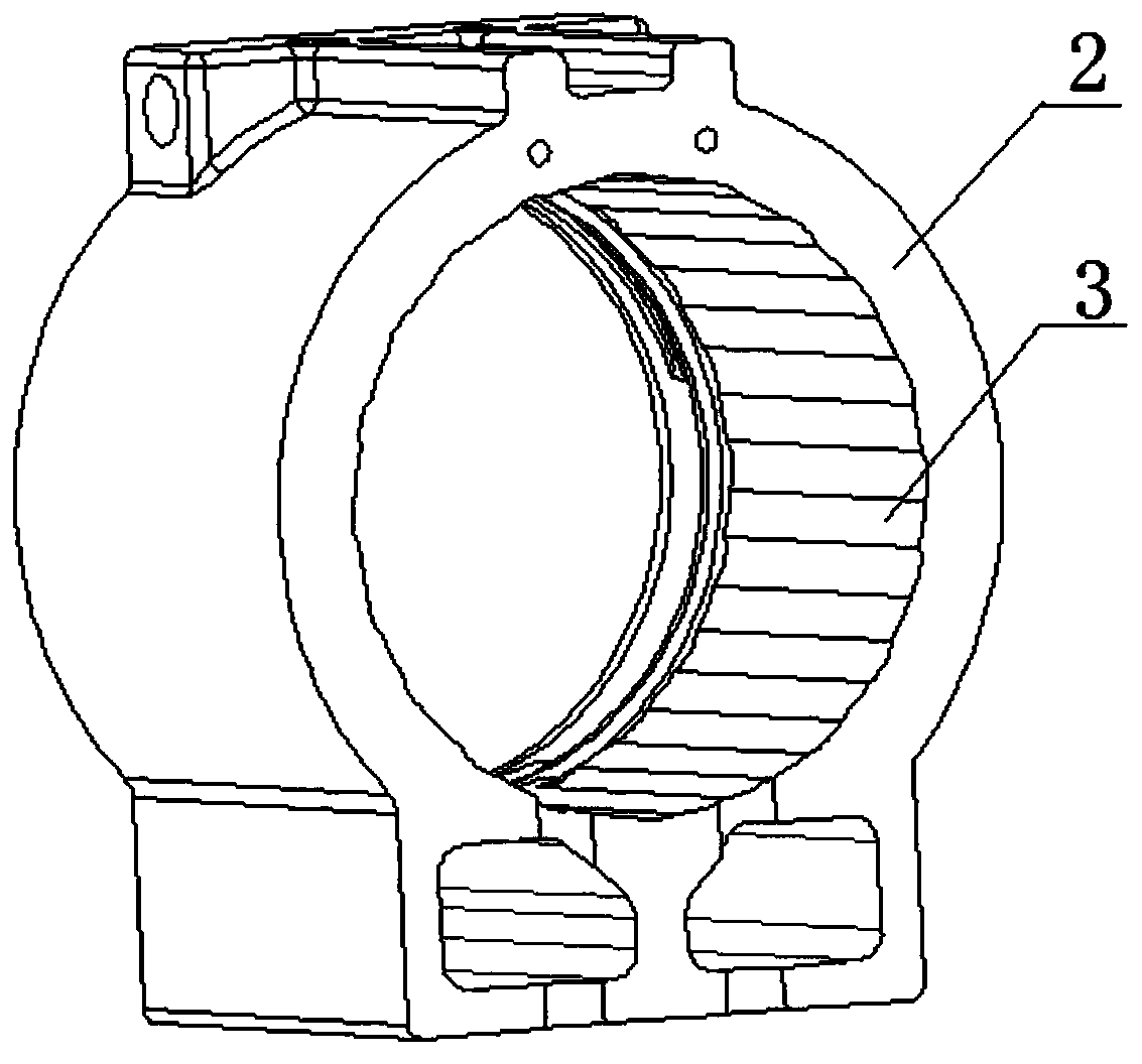
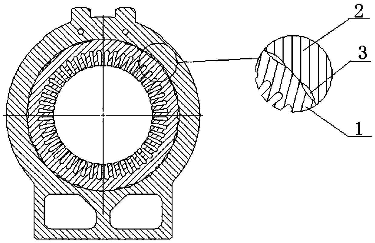
[0041] Such as Figure 1-2 As shown, a number of axial grooves 3 are distributed on the outer circumference of the stator core 1 and / or the inner circumference of the motor housing 2, and the axial grooves 3 can be groove structures of various shapes, such as arc-shaped groove, V-shaped groove, polygonal groove, etc., the axial groove 3 extends in the axial direction of the stator core 1 and / or the motor housing 2, and the axial groove 3 provided on the stator core 1 runs through the entire stator iron Core 1, the axial groove 3 provided on the motor housing 2 extends longer than the thickness of the stator core 1, and the axial groove 3 on the motor housing 2 is facing the stator core 1; the axial groove 3. The number of sets and the distribution of positions can be adjusted according to actual needs.

[0042] The stator core 1 is assemb...

Embodiment 2

[0048] The embodiment of the invention also discloses a motor cooling system, such as Figure 4-6 As shown, the motor cooling system includes a liquid inlet 5 , a liquid inlet channel 6 , a liquid separation channel, any of the stator core cooling structures described above, and a liquid outlet 8 .

[0049] The liquid inlet 5 arranged above the motor housing 2 communicates with the cooling structure of the stator core through the liquid inlet channel 6 and the liquid separation channel arranged in the motor housing 2, and the liquid outlet 8 can be provided with one or more , arranged on the lower part of the motor front end cover 9 and / or the motor rear end cover 10 and / or the lower end of the motor housing 2, so that the oil is discharged from the inside of the motor after cooling and lubricating.

[0050] In this embodiment, the oil enters the motor cooling system through the liquid inlet 5, enters the main channel 7 of the liquid distribution channel through the liquid inl...


PUM


Abstract

The invention discloses a stator core cooling structure and a motor cooling system. The stator core cooling structure comprises a stator core and a motor shell, a plurality of axial grooves are distributed on the outer circumference of the stator iron core and / or the inner circumference of the motor shell, and extend in the axial direction of the stator iron core and / or the motor shell; the statoriron core is assembled in the motor shell, and a cooling liquid channel is formed between the stator iron core and the motor shell through the axial groove, so that cooling liquid cools the stator iron core through the cooling liquid channel. According to the stator iron core cooling structure, through the cooling channel formed between the stator iron core motor shells, direct contact cooling ofthe stator iron core by oil can be achieved, the contact area is large, and the cooling efficiency is high. In addition, the axial grooves in the stator iron core are formed through punching, the cooling structure of the stator iron core is simple, and the problems that in the prior art, the machining period of slotting in the inner wall of the shell is long, the manufacturing cost is high, and the assembling process is tedious are solved.

Description

technical field [0001] The invention relates to the technical field of motors, in particular to a stator core cooling structure and a motor cooling system. Background technique [0002] At present, with the continuous development of the industry, performance requirements such as high precision and high power density are put forward for the motor, which brings serious problems of motor heating. Natural heat dissipation cannot dissipate the heat of the motor, and external forced cooling is required. [0003] The existing way to cool the inside of the motor is to slot the inner wall of the motor housing to set up a cooling oil circuit. Long processing cycle, high manufacturing cost, cumbersome assembly process and other problems. Contents of the invention [0004] In view of the existing technical problems, a stator core cooling structure and a motor cooling system of the present invention are proposed in order to solve or partially solve the above technical problems. [00...

Claims


Application Information

Patent Timeline
IPC IPC(8): H02K1/20H02K9/19H02K5/20H02K5/16H02K3/24
CPCH02K1/20H02K9/19H02K5/20H02K5/16H02K3/24H02K5/203H02K5/04H02K5/1732Y02T10/64H02K9/193
Inventor 余平凌新亮夜玉霞侯剑南王海斌
Owner JING JIN ELECTRIC TECHNOLOGIES (BEIJING) CO LTD
Learn More