Check patentability & draft patents in minutes with Patsnap Eureka AI!

Baffle structure of conveying chain of plate shearing machine and mounting method of baffle structure

A technology of baffle structure and installation method, which is applied to shearing devices, accessories of shearing machines, shearing machine equipment, etc., can solve problems such as broken thread teeth on the baffle side of fixing screws, hidden dangers of unsafety, and broken transport chains, etc. To achieve the effect of reducing transport chain breaks, reducing processing failures and significant economic benefits

Pending Publication Date: 2020-08-11
NANJING IRON & STEEL CO LTD
View PDF0 Cites 0 Cited by
  • Summary
  • Abstract
  • Description
  • Claims
  • Application Information

AI Technical Summary

Problems solved by technology

The gap between the bottom surface of the baffle and the upper surface of the conveyor chain must meet the requirements. For example, when producing a steel plate with a thickness of 5mm, the gap must be guaranteed to be 3mm. The transportation chain is broken or the edge is pulled out manually; if the gap is less than 3mm, it is easy to cause the baffle to hang on the transportation chain, causing the transportation chain to break
During the use of this kind of baffle structure, there will be about 3 times a year for each device that the fixed screw baffle side wire teeth are broken or the screws run out, causing the baffle to hang down and cause the transportation chain to break.
It takes 18 hours to replace the transportation chain every time it is broken. The unit price of a transportation chain is 80,000 yuan. The loss is huge, which seriously affects production and brings unsafe risks.

Method used


Image

  • Baffle structure of conveying chain of plate shearing machine and mounting method of baffle structure
  • Baffle structure of conveying chain of plate shearing machine and mounting method of baffle structure

Examples


Embodiment Construction

[0013] The present invention will be further described in detail below in conjunction with specific embodiments and accompanying drawings.

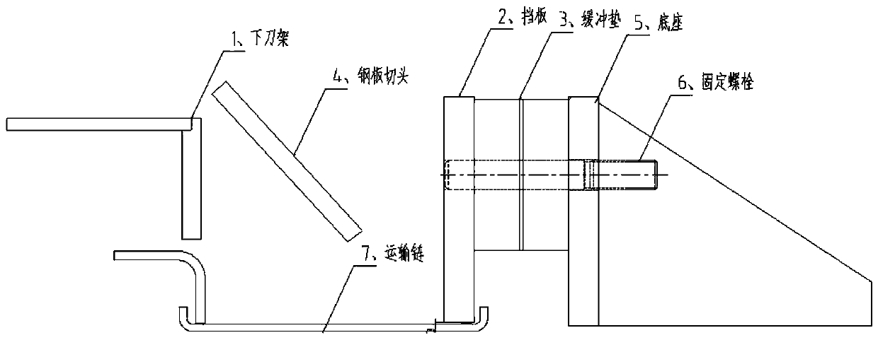
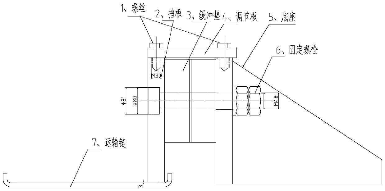
[0014] Such as figure 2 As shown, the baffle structure of the shearing machine transport chain mainly involves the improvement of two aspects:

[0015] 1. Improve the fixing bolt of the baffle: from the original double-headed bolt to a single-headed bolt with a step, this bolt has a circular step of φ80mm and 33mm long at one end, which can ensure that the bolt will not break and will not run towards the nut. , to ensure that the baffle is not loose.

[0016] 2. Add an adjustment plate that can adjust the height of the baffle: Drill holes on the top of the baffle and the base and tap the M30 screw 1, and connect the baffle 2 with the base 5 through the screw 1 and the adjustment plate 4, and pass through the adjustment plate Increase or decrease the spacer at the bottom (it is a hard spacer, aluminum and other metal sheets can be used,...


PUM


Abstract

The invention discloses a baffle structure of a conveying chain of a plate shearing machine and a mounting method of the baffle structure. The baffle structure comprises a baffle, an adjusting plate and a base, wherein a counter bore used for allowing a fixing bolt to be inserted is machined in the side face of the baffle, the diameter of the counter bore is larger than that of head step of the fixing bolt, and the depth of the counter bore is larger than that of the head step of the fixing bolt; and a through hole matched with the fixing bolt is machined in the base, threads are machined in the upper parts of the baffle and the base, and through holes matched with the threads in the upper parts of the baffle and the base are machined in the adjusting plate. According to the baffle structure of the conveying chain of the plate shearing machine and the mounting method of the baffle structure, the breakage condition of the conveying chain of the plate shearing machine can be reduced to the maximum extent, so that the safety risks of fault handling by workers and manual steel plate cut head pulling are reduced, the spare part cost also is greatly saved, the production efficiency is improved, and the economic benefit is remarkable.

Description

technical field [0001] The invention belongs to the technical field of metal processing machinery and relates to a shearing machine. Background technique [0002] The shearing machine is the main equipment of the medium and thick plate factory. Its function is to cut the longitudinal or transverse edge of the steel plate to make the length and width of the steel plate meet the needs of users. The longitudinal or transverse steel plate cut ends produced during the shearing process must be transported to the waste pit outside the shearing body in time, otherwise the production cannot be carried out. [0003] Such as figure 1 Shown is the original structure diagram of the baffle of the transport chain of the shearing machine: the sheared steel plate cutting head falls from the lower knife rest to the transport chain, and is transported by the transport chain to the waste pit outside the shear body. In order to ensure that the cutting head of the steel plate just falls on the ...

Claims


Application Information

Patent Timeline
Patent Type & Authority Applications(China)
IPC IPC(8): B23D33/00B23D15/06
CPCB23D15/06B23D33/00
Inventor 俞美萍顾玉芳
Owner NANJING IRON & STEEL CO LTD
Features
  • R&D
  • Intellectual Property
  • Life Sciences
  • Materials
  • Tech Scout
  • Unparalleled Data Quality
  • Higher Quality Content
  • 60% Fewer Hallucinations
Learn More