Chromium-plated linear optical shaft batch machining and processing system

A technology of linear optical axis and processing system, which is applied in the direction of metal processing equipment, metal processing machinery parts, manufacturing tools, etc., can solve the problems of large cutting area, long mechanical no-load time, long return time, etc., to improve the firmness of clamping Sexuality, the effect of improving batch cutting efficiency

Inactive Publication Date: 2020-08-11
张明杰
View PDF1 Cites 0 Cited by
  • Summary
  • Abstract
  • Description
  • Claims
  • Application Information

AI Technical Summary

Problems solved by technology

[0006] In view of the problems in the prior art, the object of the present invention is to provide a batch processing system for chrome-plated linear optical axes, which solves the current batch cutting process for chrome-plated linear optical axes, which is mainly cut by mechanical cutting. Yes, when the machine cuts chrome-plated linear optical shafts in batches, because the cutting area is large when cutting chrome-plated linear optical shafts in batches, it takes a long time for the machine to return after the cutting and feeding is completed, the production efficiency is low, and the mechanical no-load time is long. , a technical problem that wastes production resources

Method used


Image

  • Chromium-plated linear optical shaft batch machining and processing system
  • Chromium-plated linear optical shaft batch machining and processing system
  • Chromium-plated linear optical shaft batch machining and processing system

Examples


Embodiment Construction

[0034] In order to make the technical means, creative features, goals and effects achieved by the present invention easy to understand, the present invention will be further elaborated below in conjunction with specific drawings. It should be noted that, in the case of no conflict, the embodiments and Features in the embodiments can be combined with each other.

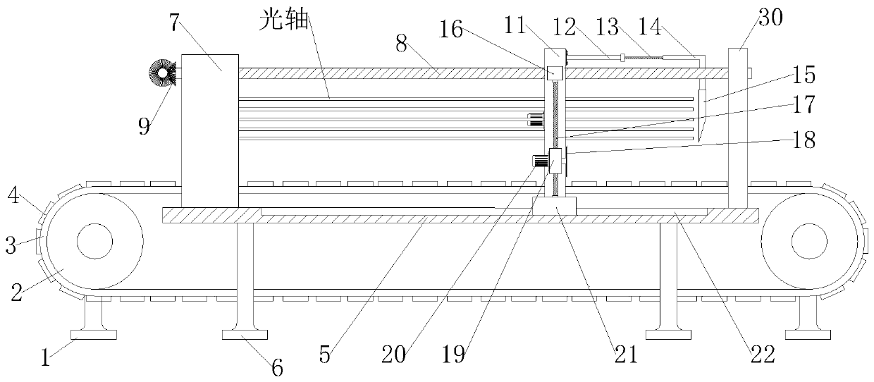
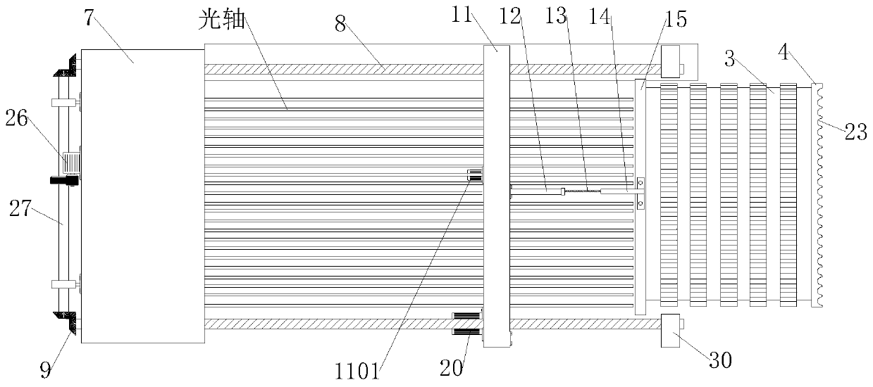
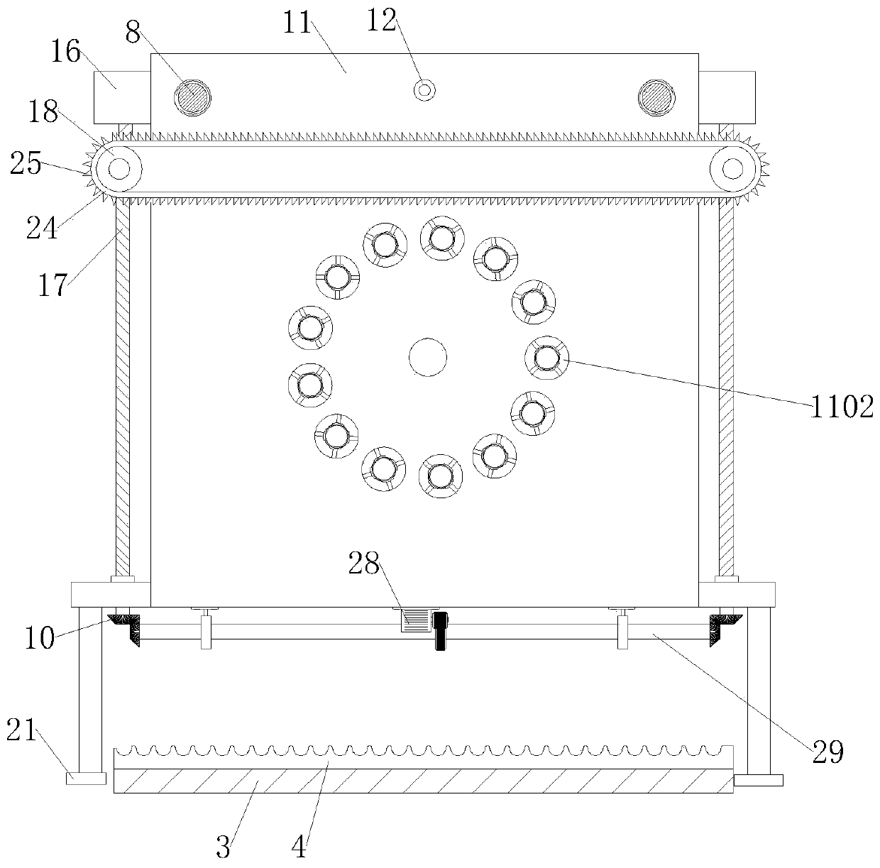
[0035] see Figure 1-8 , is a specific structural schematic diagram of an embodiment of the description of the present invention;

[0036] A chrome-plated linear optical axis batch processing system, including a circularly rotating conveyor belt 3, and a sliding frame 11 installed on the top of the conveyor belt 3, the conveyor belt 3 is placed horizontally on the ground, and the left and right ends of the inner ring of the conveyor belt 3 A drum 2 is provided, and the two ends of the drum 2 are installed and fixed with a first foot 1 through bearings. The first foot 1 is fixed on the ground, and the outer wall of th...


PUM


Abstract

The invention provides a chromium-plated linear optical shaft batch machining and processing system, and relates to the technical field of machining. The system comprises a conveying belt which rotates circularly and a sliding rack installed at the top end of the conveying belt, wherein rollers are arranged at the left end and right end of an inner ring of the conveying belt; first feet are installed and fixed at the two ends of the rollers through bearings; and a plurality of optical shaft brackets are arranged on the outer wall of the conveying belt at equal intervals. According to the chromium-plated linear optical shaft batch machining and processing system, two fixed supporting rods and one movable rod are arranged in each clamping hole of the sliding rack, and the top ends of the twofixed supporting rods and the top end of the movable rod are each hinged with a movable clamping claw which is bent in an arc shape; and through the hinge and swing of every two movable clamping claws, the adaptive clamping is carried out through the automatic swing of the movable clamping claws when the corresponding movable rod stretches and retracts in the corresponding clamping hole, so thata chromium-plated linear optical shaft installed in each clamping hole is clamped and fixed, and the clamping firmness of the chromium-plated linear optical shafts is improved.

Description

technical field [0001] The invention relates to the technical field of optical shaft processing, in particular to a batch processing system for chrome-plated linear optical shafts. Background technique [0002] The linear optical axis is a product that has a guiding function of a sliding bearing and can perform linear motion. The necessary conditions required by these linear motion systems are: simple design, best execution ability, low maintenance cost, use of strictly selected strong and durable materials, high frequency heat treatment, accurate outer diameter size, roundness, and straightness and surface treatment, etc., [0003] Chrome-plated linear optical shaft: Chrome-plated linear optical shaft is coated with a layer of hard chrome on the basis of ordinary linear optical shaft, also known as bearing rod, which is suitable for rust-prone environment or bad environment. This shaft is widely used in industrial machinery Human, the moving part of the automatic sliding ...

Claims


Application Information

Patent Timeline
Patent Type & Authority Applications(China)
IPC IPC(8): B23D79/00B23Q3/00
CPCB23D79/00B23Q3/00B23Q2703/10
Inventor 张明杰陈栋
Owner 张明杰
Why Eureka
Try Eureka