Discharging mechanism of blood collection tube conveying line

A technology for blood collection tubes and conveyor lines, which is applied in the direction of conveyors, conveyor objects, transportation and packaging, etc., and can solve the problems of slow feeding of blood collection tubes, increased workload of medical staff, and large volume

Pending Publication Date: 2021-08-31
广州景禾医疗科技有限公司
View PDF0 Cites 0 Cited by
  • Summary
  • Abstract
  • Description
  • Claims
  • Application Information

AI Technical Summary

Problems solved by technology

The traditional manual cutting of batches of blood collection tubes is slow, inefficient, large in accidental errors, and cannot achieve full automation, which increases the workload of medical staff
In addition, there are some automatic tube spli

Method used


Image

  • Discharging mechanism of blood collection tube conveying line
  • Discharging mechanism of blood collection tube conveying line
  • Discharging mechanism of blood collection tube conveying line

Examples


Embodiment approach

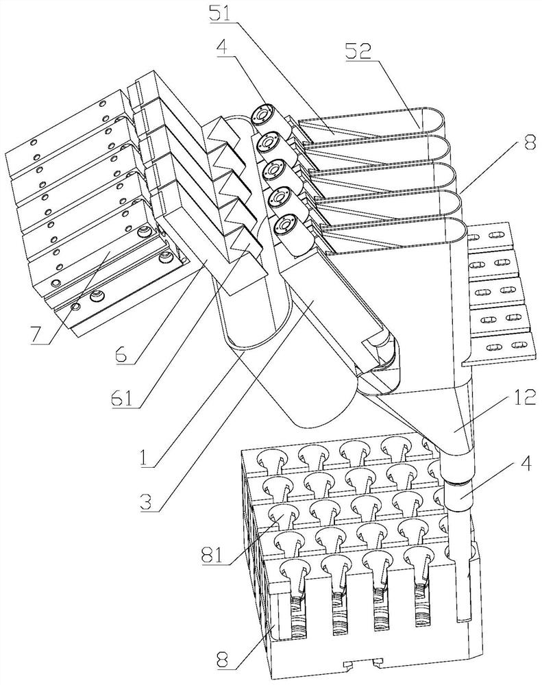
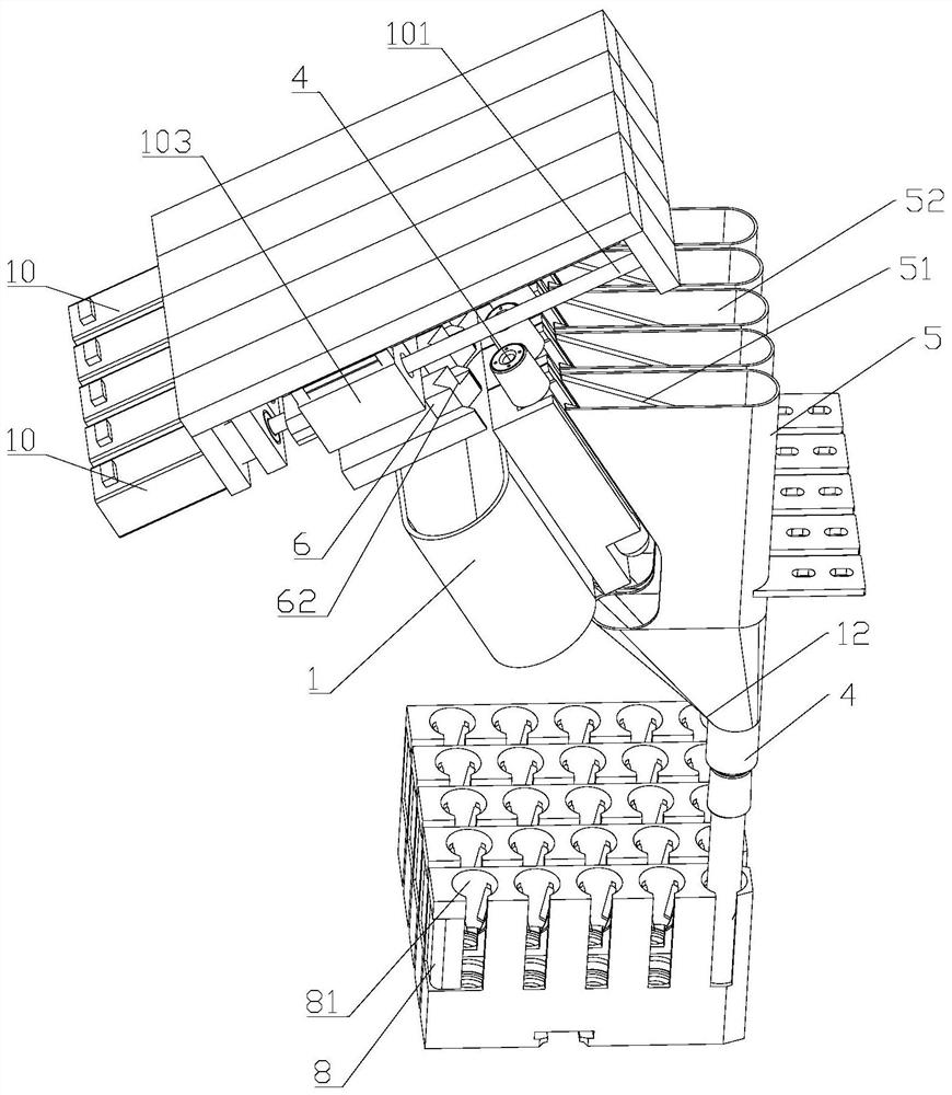
[0036] According to another specific embodiment of the present invention, the driving mechanism includes a stepping motor 10, a screw rod 101, and a moving nut 102; the power output end of the stepping motor 10 is fixedly connected to one end of the screw rod 101, and the moving nut 102 is sleeved on the screw rod 101 And be fixedly connected with pushing block 6. Such as figure 2 As shown, in the present embodiment, the power output end of the stepper motor 10 drives a screw 101 to rotate, thereby driving the moving nut 102 to move back and forth along the screw 101. Since the moving nut 102 is fixed to the push block 6, the push block 6 follows The blood collection tube 4 on the jig 3 is pushed back and forth back and forth by the moving nut 102 to accurately slide into the guide groove 52 .

[0037] According to another specific embodiment of the present invention, a second groove 62 is provided on an end surface of the push block 6 close to the blood collection tube 4 . ...

specific Embodiment approach

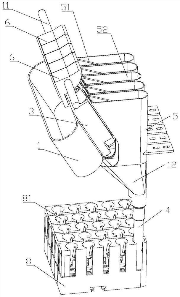
[0038] According to another specific embodiment of the present invention, the driving mechanism includes a toggle motor and a toggle shaft 11, the toggle shaft 11 and the toggle motor are located outside the clamping opening, the push block 6 is fixed on the toggle shaft 11, and the toggle One end of the shaft 11 is fixedly connected with the power output end of the toggle motor. Such as image 3 As shown, the toggle motor (not shown in the accompanying drawings) can be selected from various types of motors, such as asynchronous motors, etc., the power output end of the toggle motor drives the toggle shaft 11 to rotate, and the toggle shaft 11 passes through the opening of the push block 6 One end is fixedly connected with it, so the push block 6 is driven to move the blood collection tube 4 on the jig 3 to advance and slide into the guide groove 52 during the rotation of the toggle shaft 11 .


PUM


Abstract

The invention discloses a discharging mechanism of a blood collection tube conveying line, and belongs to the technical field of blood collection tube processing. The discharging mechanism of the blood collection tube conveying line comprises a conveying assembly, a material guiding assembly, a material pushing assembly and a storage assembly, wherein the conveying assembly comprises a conveying belt, a driving motor and a jig, the conveying belt is driven by the driving motor, the jig is in a long-strip box shape, and a plurality of openings are formed in the front end face, the upper end face and the lower end face of the jig to form a plurality of clamping openings; the material guiding assembly comprises a material guiding box, a plurality of partition plates and a plurality of feeding hoppers, openings are formed in the front side face, the lower end face and the upper side face of the material guiding box, the plurality of partition plates are vertically arranged in the material guiding box at equal intervals and divide the material guiding box into a plurality of material guiding grooves, and the widths of upper hopper openings of the feeding hoppers are matched with the widths of the material guiding grooves; the material pushing assembly comprises a plurality of pushing blocks and a plurality of driving mechanisms for driving the pushing blocks to push blood collection tubes to advance; and the storage assembly comprises a plurality of storage boxes. The discharging mechanism is simple in structure, accurate in discharging and low in input cost, and the batch feeding efficiency of the blood collection tubes is greatly improved.

Description

technical field [0001] The invention relates to the technical field of blood collection tube processing, in particular to a feeding mechanism for a blood collection tube conveying line. Background technique [0002] In the existing blanking process of vacuum blood collection tubes, it is usually completed by manual blanking, that is, manual tube division. The traditional manual cutting of batches of blood collection tubes is slow, inefficient, and has large accidental errors, and cannot achieve full automation, which increases the workload of medical staff. In addition, there are some automatic tube splitting machines in use on the market that can effectively realize the function of cutting blood collection tubes, but they are large in size and complex in internal structure, which is not conducive to staff repair and maintenance, and the input cost is high. Contents of the invention [0003] In order to overcome the defects of the prior art, the technical problem to be so...

Claims


Application Information

Patent Timeline
IPC IPC(8): B65G15/58B65G23/22B65G11/02B65G47/82B65G65/32
CPCB65G11/023B65G15/58B65G23/22B65G47/82B65G65/32B65G2201/0235
Inventor 孙军
Owner 广州景禾医疗科技有限公司
Why Eureka
Try Eureka