
Sludge treatment system and method

A sludge treatment and sludge technology, applied in the direction of sludge treatment, water/sludge/sewage treatment, dehydration/drying/thickened sludge treatment, etc., can solve the inconvenience of promoting the sludge treatment system and the occupation of the sludge treatment system Large area, affecting sludge treatment efficiency and other issues

Inactive Publication Date: 2020-08-11
四川金土源环保科技有限公司
View PDF4 Cites 1 Cited by
  • Summary
  • Abstract
  • Description
  • Claims
  • Application Information

AI Technical Summary

Problems solved by technology

[0005] Aiming at the deficiencies of the prior art, the present invention provides a sludge treatment system and a treatment method, which can integrate all parts of the sludge treatment system, so that the sludge treatment does not need to be transported back and forth, saving time and effort, and reducing the workload. The labor intensity of personnel, and can effectively improve the efficiency of sludge treatment in the sludge treatment system, and reduce the floor area of ​​the sludge treatment system, can facilitate the promotion of the sludge treatment system, etc., solve the problems of various equipment in the sludge treatment system It is scattered and needs to transfer sludge to various treatment locations. The transfer process is time-consuming and laborious, which increases the labor intensity of the staff and affects the efficiency of sludge treatment. At the same time, the sludge treatment system occupies a large area and is not convenient for the sludge treatment system. promotion problem

Method used


Image

  • Sludge treatment system and method
  • Sludge treatment system and method
  • Sludge treatment system and method

Examples


Embodiment Construction

[0027] The technical solutions in the embodiments of the present invention will be clearly and completely described below. Obviously, the described embodiments are only some of the embodiments of the present invention, but not all of them. Based on the embodiments of the present invention, all other embodiments obtained by persons of ordinary skill in the art without making creative efforts belong to the protection scope of the present invention.

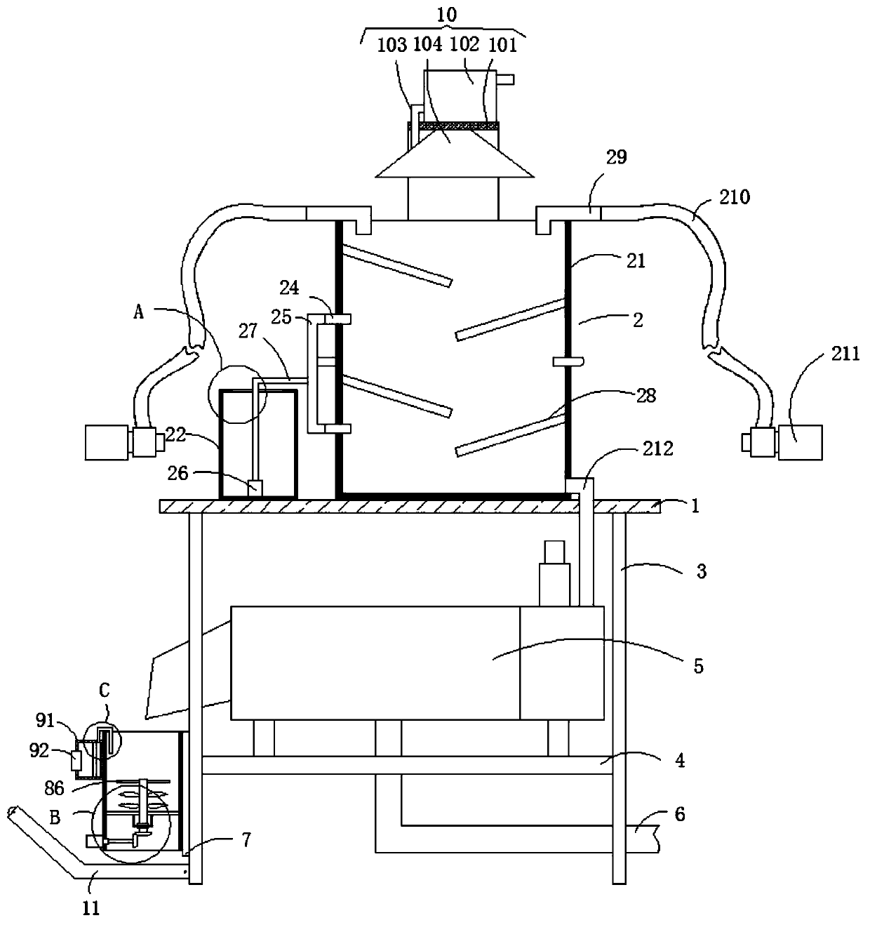
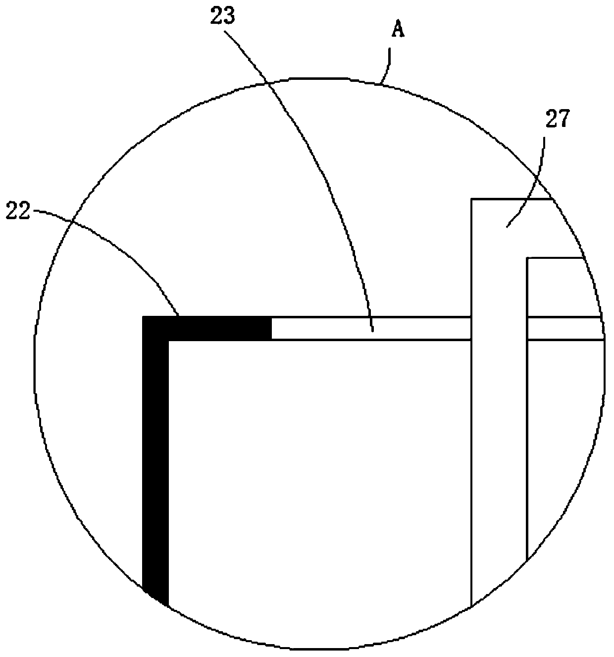
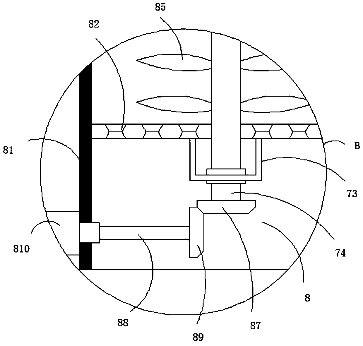
[0028] see Figure 1-4 , a sludge treatment system, comprising a workbench 1, a sterilizing mechanism 2 is fixedly connected to the upper surface of the workbench 1, support legs 3 are fixedly connected to the four corners of the lower surface of the workbench 1, and the outer walls of the plurality of support legs 3 are common A support plate 4 is fixedly connected, the upper surface of the support plate 4 is fixedly connected with a sludge dewatering screw stacker 5, and the outlet end of the sludge dewatering screw stacker 5 is f...


PUM


Abstract

The invention relates to the technical field of sludge treatment. The invention further discloses a sludge treatment system and a sludge treatment method. The system comprises a workbench, and the upper surface of the workbench is fixedly connected with a sterilization mechanism. Supporting legs are fixedly connected to the four corners of the lower surface of the workbench. The outer walls of themultiple supporting legs are jointly and fixedly connected with a supporting plate. The upper surface of the supporting plate is fixedly connected with a sludge dewatering screw stacking machine, andthe water outlet end of the sludge dewatering screw stacking machine is fixedly communicated with a return pipe. The outer walls of two of the supporting legs are fixedly connected with a fixing plate, and the outer wall of the fixing plate is fixedly connected with a crushing mechanism. According to the sludge treatment system and method, all parts in the sludge treatment system are integrated together, so that back-and-forth transfer is not needed in sludge treatment, time and labor are saved, the labor intensity of workers is reduced, the sludge treatment efficiency of the sludge treatmentsystem can be effectively improved, the occupied area of the sludge treatment system is reduced, and popularization of the sludge treatment system can be facilitated.

Description

technical field [0001] The invention relates to the technical field of sludge treatment, in particular to a sludge treatment system and a treatment method. Background technique [0002] Sludge treatment is the process of thickening, regulating, dehydrating, stabilizing, drying or incinerating sludge. There are many methods to deal with oily sludge. Chemical and physical methods such as: incineration, chlorine oxidation, ozone oxidation And combustion, biological treatment methods such as: bioremediation, traditional composting, etc. Now, with the development of technology, low-temperature cold treatment and bioremediation of oily sludge have become two effective treatment methods. Raw sludge refers to untreated The primary sedimentation sludge of sludge treatment, the secondary sedimentation sludge refers to the sediment discharged from the secondary sedimentation tank. [0003] The equipment in the existing sludge treatment system is scattered, and the sludge needs to be t...

Claims


Application Information

Patent Timeline
Patent Type & Authority Applications(China)
IPC IPC(8): C02F11/00C02F11/125C02F11/13B02C18/00B02C18/12
CPCC02F11/004C02F11/125C02F11/13B02C18/0084B02C18/12
Inventor 张上张克俭
Owner 四川金土源环保科技有限公司
Learn More