Functional rainwater garden suitable for sponge cities

A rain garden, sponge city technology, applied in drinking water installations, general water supply conservation, runoff/rainwater treatment, etc., can solve problems such as rare products and less research on soil components

Pending Publication Date: 2020-08-11
SHANGHAI INSTITUTE OF TECHNOLOGY +1
View PDF0 Cites 0 Cited by
  • Summary
  • Abstract
  • Description
  • Claims
  • Application Information

AI Technical Summary

Problems solved by technology

At present, domestic and foreign research mainly focuses on the utilization of urban solid waste in terrain, garden buildings, roads,

Method used


Image

  • Functional rainwater garden suitable for sponge cities
  • Functional rainwater garden suitable for sponge cities
  • Functional rainwater garden suitable for sponge cities

Examples


Embodiment 1

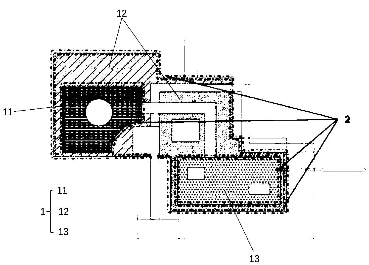
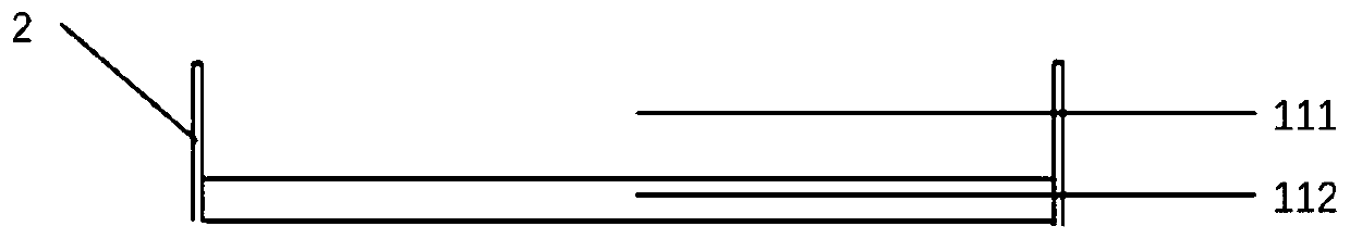
[0033] see Figure 4 As shown, this embodiment provides a functional rain garden suitable for sponge cities. The entire functional rain garden system covers an area of ​​about 100-400 square meters. The entire functional rain garden plane is mainly divided into two major areas. One large area is the multi-level baffle area 1 that is connected in series and the height is gradually decreased step by step, and the second largest area is the overflow partition wall 2 set between the multi-level baffle areas 1; the multi-level baffle area 1 includes the first level The baffle area 11 (area A on the figure), two intermediate baffle areas 12 (areas B and C on the figure) and the final baffle area 13 (area D on the figure), the first stage baffle area Between 11 and the intermediate baffle area 12, between the intermediate baffle area 12, between the intermediate baffle area 12 and the final baffle area 13, there are overflow partition walls 2, and on the overflow partition wall 2 An...

Embodiment 2

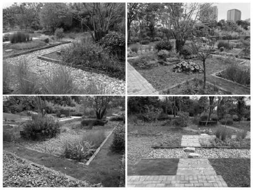
[0038] see Figure 5 to Figure 7 As shown, this embodiment selects the east side of the S18 plot in Jinqiao Park as a demonstration site, and provides a functional rain garden suitable for sponge cities, with an area of ​​about 400 square meters. The site was originally a lawn-based site. Small-scale green space, the soil matrix is ​​mixed with a lot of construction waste, the water permeability of the site is poor, the surface runoff basically flows into the water body on the west side after passing through the road on the west side, and flushes a large amount of pollutants in the surrounding area into the water body, which increases the Pollution load of water bodies. Based on the idea of ​​stormwater control, the shape of the site has been deeply transformed, and the area has been transformed into a rain garden demonstration area, which can not only improve the comprehensive effect of the site, but also accommodate the surrounding sites (including the parking lot on the eas...


PUM

PropertyMeasurementUnit
Thicknessaaaaaaaaaa
Thicknessaaaaaaaaaa
Thicknessaaaaaaaaaa

Abstract

The invention discloses a functional rainwater garden suitable for sponge cities. The functional rainwater garden suitable for the sponge cities comprises multiple stages of baffling areas which are sequentially connected in series and are gradually decreased in height, the multiple stages of baffling areas comprise a first-stage baffling area, a plurality of middle-stage baffling areas and a last-stage baffling area, wherein the first-stage baffling area and the middle-stage baffling areas are sequentially provided with a first water storage layer and a first covering layer from top to bottom, the last-stage baffling area is sequentially provided with a second water storage layer, a second covering layer, a planting soil layer, a medium sand filtering layer, geotechnical cloth, a storageand seepage layer, a gravel drainage layer and a seepage pipe from top to bottom, the first covering layer and the second covering layer contain gravel and construction waste particles, and the storage and seepage layer is made of construction waste. According to the functional rainwater garden suitable for the sponge cities, the construction waste is used for construction of the covering layers and the storage and seepage layer so that the stacking problem of the construction waste can be solved, the disposal cost is saved, environmental pollution is reduced, moreover, a greenbelt can be usedfor stopping and storing rainwater for infiltration on site, then the rainstorm runoff peak value and rainwater drainage are reduced, and underground water recharging is increased.

Description

technical field [0001] The invention belongs to the field of highway engineering construction, in particular to a functional rainwater garden suitable for sponge cities. Background technique [0002] Since the Second World War, the urbanization of countries all over the world has developed rapidly and has shown a trend of rapid expansion. Two major urban problems have emerged. One is that a large amount of construction waste is produced every year; With the deepening of garbage classification, special garbage treatment will enter the era of targeted treatment. At present, the amount of urban construction waste in my country has accounted for 30% to 40% of the total urban garbage. With the acceleration of urbanization, a large number of engineering construction The total amount of construction waste will continue to increase. How to discharge and deal with urban construction waste has become an important issue faced by construction companies and environmental protection depart...

Claims


Application Information

Patent Timeline
IPC IPC(8): E03F5/00E03F5/10E03F1/00E03B3/02C02F9/14
CPCC02F1/001C02F1/28C02F3/32C02F9/00C02F2001/007C02F2103/001E03B3/02E03F1/002E03F5/00E03F5/10Y02A10/30Y02A20/108
Inventor 傅妍榕贺坤邹维娜宰正浩王辉
Owner SHANGHAI INSTITUTE OF TECHNOLOGY
Why Eureka
Try Eureka