Advance guide pipe driving device for underground excavation trolley

A trolley and leading technology, applied in the direction of supporting devices, shaft equipment, shaft lining, etc., can solve the problems of high labor intensity, leading pipe bending, shallow penetration depth, etc., to facilitate installation and disassembly, and reduce labor Strength, work efficiency improvement effect

Pending Publication Date: 2020-08-11
徐州徐工铁路装备有限公司
0 Cites 0 Cited by

AI-Extracted Technical Summary

Problems solved by technology

[0004] Manual construction is inefficient and labor-intensive, and the penetration depth is shallow, making it difficult to meet the construction requirements; and when the construction geology is sandy pebbles and other strata, it ...

Abstract

The invention discloses an advance guide pipe driving device for an underground excavation trolley. The device comprises a beam body, a rock drill, a drilling oil cylinder, a movable pulley block, a clamping device, an advance guide pipe, a base and a propelling oil cylinder, and the rock drill is arranged on the beam body in a sitting manner and is connected with the beam body in a sliding manner. The advance guide pipe is fixedly connected with the rock drill and driven by the rock drill to rotate; the rock drill advances and retreats under the driving of the movable pulley block through thedrilling oil cylinder arranged in the beam body; and the propelling oil cylinder is matched with the base and is suitable for driving a longer advanced guide pipe. By means of the structure, advanceguide pipe driving is more convenient, and construction quality and construction efficiency are improved.

Application Domain

Underground chambersDerricks/masts +2

Technology Topic

Geotechnical engineeringBlock and tackle +3

Image

  • Advance guide pipe driving device for underground excavation trolley
  • Advance guide pipe driving device for underground excavation trolley
  • Advance guide pipe driving device for underground excavation trolley

Examples

  • Experimental program(1)

Example Embodiment

[0036] The present invention will be further described in detail below with reference to the accompanying drawings and specific embodiments.
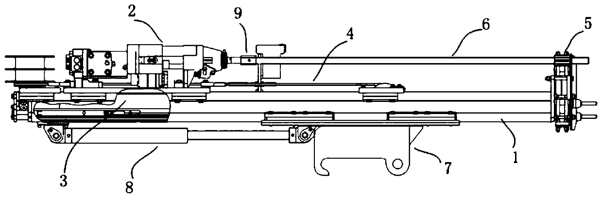
[0037] First of all, let me explain that the direction mentioned in the technical plan is in figure 1 The left side of the middle screen is the rear or rear end of each device, and the right side of the screen is the front or front end of each device, which facilitates a clear description of the technical solution.
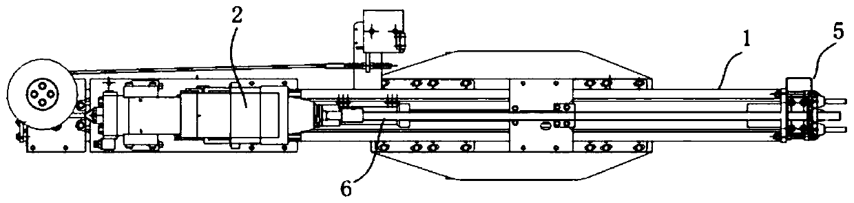
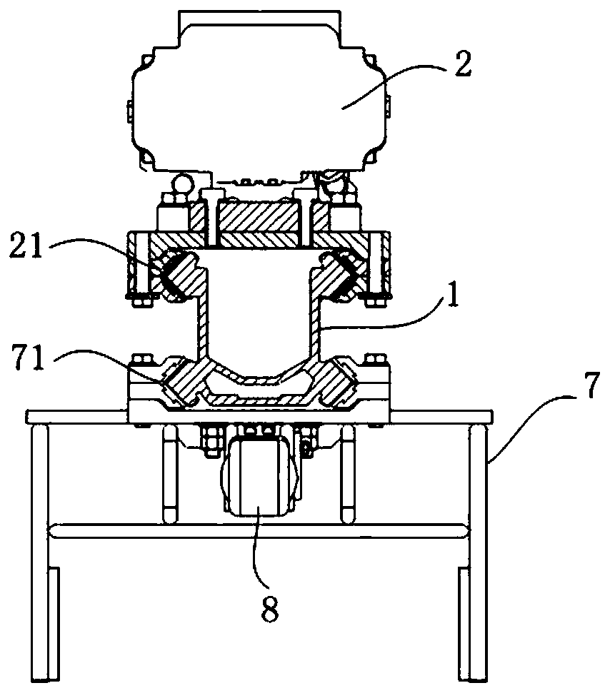
[0038] like Figure 1-13 As shown in the figure, a lead pipe device for drilling a trolley, comprising a beam body 1, a rock drill 2, a drilling oil cylinder 3, a movable pulley block 4, a clamping device 5 and a lead pipe 6, wherein the beam body 1 is as shown in the figure. Figure 4-6 As shown, it is a long strip structure, the right side is the front end, the left side is the rear end, and the material is made of aluminum alloy. The rock drill 2 is seated on the beam body 1 and is slidably connected with the beam body 1 . The leading conduit 6 is fixedly connected with the rock drill 2 and is driven to rotate by the rock drill 2 . Specifically, the leading conduit 6 is fixedly connected with the rock drill 2 through the connecting sleeve 9 . The rock drill 2 moves forward and backward under the driving of the movable pulley block 4 through the drilling oil cylinder 3 arranged in the beam body 1 . Among them, such as image 3 As shown, a first slideway 11 is provided on the outer side of the upper part of the beam body 1 , and a first slideway 21 is provided at the lower part of the rock drill, and the first slideway 21 cooperates with the first slideway 11 to slide. like Figure 7-8 As shown, the drilling oil cylinder 3 includes a cylinder block 31 and a cylinder rod 32 , the cylinder rod 32 is fixed at the rear end of the beam body 1 , and the cylinder block 31 moves back and forth relative to the cylinder rod 32 . The movable pulley block 4 includes a front-end movable pulley mechanism 41 and a forward wire rope 42, a rear-end movable pulley mechanism 43 and a backward wire rope 44. The front-end movable pulley mechanism 41 is located in the middle of the beam body 1, and the front-end movable pulley mechanism 41 includes a front-end movable pulley 41-1 and a front-end mounting plate 41-2. and the second chute 41-3, the front movable pulley 41-1 and the second chute 41-3 are fixedly connected to the front mounting plate 41-2; the second chute 41-3 cooperates with the first chute 11 to slide. The advancing wire rope 42 is wound around the front movable pulley 41 - 1 , one end is fixed on the rock drill 2 , and the other end is fixed on the rear end of the beam body 1 . The rear end movable pulley mechanism 43 is arranged on the upper part of the rear end of the cylinder block 31. The rear end movable pulley mechanism 43 includes a rear end movable pulley 43-1, and the backward wire rope 44 bypasses the rear end movable pulley 43-1, one end of which is fixedly connected with the rear end of the rock drill 2, and the other end Fixed on one side of the beam body 1. The rear-end moving pulley mechanism 43 also includes a rear-end mounting plate 43-2, a third chute 43-3 and a cable winding column 43-4. The third sliding slot 43-3 cooperates with the first slideway 11 to slide, wherein the cable is wound around the column. 43-4 is used for cables and oil pipes on rock drills to prevent them from being entangled by other equipment when advancing and retreating.
[0039] like Figure 11 As shown, it is the structure of the first chute 21, the second chute 41-3, the third chute 43-3, and the fourth chute 71 are also of the same structure. The triangular convex grooves of the first slideway 11 and the second slideway 12 are matched with each other.
[0040] like Figure 12-13As shown, the clamping device 5 is fixedly arranged at the front end of the beam body 1 for clamping the leading conduit 6. The clamping device 5 includes an upper clamping sleeve 51, a lower clamping sleeve 52, a clamping oil cylinder 53 and a bottom plate 54. The clamping sleeve 51 is fixedly connected to the bottom plate 54 , the lower clamping sleeve 52 is fixedly connected to the clamping cylinder 53 , and the lower clamping sleeve 52 is closed and opened with the upper clamping sleeve 51 under the extension and retraction of the clamping cylinder 53 . After the drilling of the conduit is completed, the clamping device 5 clamps the leading conduit 6, and the rock drill 2 is reversed, so that the threaded connection between the connecting sleeve 9 and the leading conduit 6 is disengaged. After the disconnection is completed, the clamping device 5 is released from the clamping, the drilling oil cylinder 3 is retracted, and under the pulling force of the rear end wire rope 44, the rock drill 2 retreats, and the leading conduit 6 is re-installed to carry out the next cycle of drilling the leading conduit. .
[0041] The above structure generally describes the leading pipe device, wherein the movable pulley block 4 can make the stroke of the rock drill 2 twice as long as the stroke of the drilling cylinder 3 . The rock drill 2 can drive the advance conduit 6 to rotate forward, so that the stones can be moved away when encountering sand and pebble formations, without causing the advance conduit to bend.
[0042] The device further includes a base 7 , a second slideway 12 is provided on the outer side of the lower part of the beam body 1 , a fourth slideway 71 is provided on the basement 7 , and the third slideway 71 cooperates with the second slideway 12 to slide. The device also includes a propelling oil cylinder 8, one end of the propelling oil cylinder 8 is fixed at the bottom of the rear end of the beam body 1, and one end is fixedly connected with the base 7. The front end of the cylinder block 31 is provided with an extension rod 33, and the extension rod 33 is fixedly connected with the front end mounting plate 41-2.
[0043] By adding the base 7 and the propulsion cylinder 8, when the length of the advance duct 6 needs to be extended for drilling (the length of the extension is not greater than the stroke of the propulsion cylinder 8), the head of the advance duct 5 is aligned with the position to be drilled, and the advance duct 5 is first drilled through the advance cylinder 8 The pulling force drives the beam body to move forward as a whole, so that the rotating advance guide pipe is drilled into the soil layer until it reaches the stroke of the propulsion cylinder 8; then start the drilling cylinder 3, so that the front end wire rope 42 gives the rock drill 2 a pulling force, and continues to drill. When the drilling cylinder 3 is extended to the limit, the drilling is completed. When the drilling resistance is relatively large, the rock drill 2 can provide a certain frequency of impact force to overcome the resistance.
[0044] In addition, the device also includes a displacement sensor, and the displacement sensor is installed at the rear end of the beam body 1 . It is used to measure the length of the part of the lead duct 6 which is driven into the soil layer. The displacement sensor is a pull-wire type, and its outgoing end is connected to the rock drill 2. The displacement sensor measures the length of the line extending, which is the advancing distance of the rock drill 2, that is, the length of the leading conduit 6 drilled into the soil layer.
[0045] like Figure 14-15 As shown, for the drilling oil cylinder, the drilling oil cylinder 3 also includes a steel pipe 34, the cylinder rod 32 is hollow inside, and the steel pipe 34 passes through the hollow part of the cylinder rod 32 to supply oil to the rodless cavity of the cylinder block 31; the cylinder rod 32 is hollow The part supplies oil to the rod cavity of the cylinder block 31 . The tail end of the cylinder rod 32 is provided with two oil inlets, one of which supplies oil to the rodless cavity through the steel pipe 34, and the other enters the oil through the hollow part of the cylinder rod. There is an oil outlet on the cylinder rod arm, which is the cylinder block 31. The rod cavity is supplied with oil. The rodless cavity supplies oil to advance the cylinder body 31, and the rod cavity supplies oil to make the cylinder body 31 retreat, thereby driving the rock drill 2 to advance and retreat. This structural design of the drilling oil cylinder 3 enables the installation of the movable pulley block to have a focal point and provides a strong support for the cooperation of the two.
[0046] The embodiments of the present invention have been described in detail above in conjunction with the accompanying drawings, but the present invention is not limited thereto. Within the scope of knowledge possessed by those skilled in the art, various Variations are all within the protection scope of the claims of the present invention.

PUM

no PUM

Description & Claims & Application Information

We can also present the details of the Description, Claims and Application information to help users get a comprehensive understanding of the technical details of the patent, such as background art, summary of invention, brief description of drawings, description of embodiments, and other original content. On the other hand, users can also determine the specific scope of protection of the technology through the list of claims; as well as understand the changes in the life cycle of the technology with the presentation of the patent timeline. Login to view more.

Similar technology patents

Charging bow type electric car charging system

Owner:凯迈(洛阳)电子有限公司

Full-automatic part sorting and conveying system

ActiveCN105364450AReduce labor intensityImprove work efficiency and precision
Owner:DONGGUAN TIANFU LIDE IND CO LTD

Classification and recommendation of technical efficacy words

  • Reduce labor intensity
  • Improve work efficiency

Method for intelligent automatic identification of transmission circuit parts

Owner:INFORMATION COMM COMPANY STATE GRID SHANDONG ELECTRIC POWER +2

City regional railway signal system and control method thereof

Owner:CHINA RAILWAY SIYUAN SURVEY & DESIGN GRP

Railway bearing intelligent on-line detection method and its device

InactiveCN101290265AReduce labor intensity
Owner:洛阳铭昊测控科技有限公司

Cooperation service platform facing different source data

InactiveCN101174957AImprove management level and qualityImprove work efficiency
Owner:NANJING UNIV OF FINANCE & ECONOMICS

Screw drilling tool, vertical drilling tool testing method and well inclination simulation testing equipment

InactiveCN111594144AReduced height requirementsImprove work efficiency
Owner:DEZHOU UNITED GASOLINEEUM MACHINERY

Method for intelligent automatic identification of transmission circuit parts

Owner:INFORMATION COMM COMPANY STATE GRID SHANDONG ELECTRIC POWER +2

Keyboard spill-proofing mechanism

ActiveUS7030330B2minimize manufacturing costimprove work efficiency
Owner:LITE ON SINGAPORE PTE LTD
Why Eureka
Try Eureka