
Recovery system and recovery method of residual pressure and residual heat in backpressure heat supply unit

A heating unit and recovery system technology, applied in heat recovery systems, steam recovery, heat exchangers, etc., can solve the problems of water and heat loss, white smoke, pressure energy waste and other problems in the thermal system, and achieve the reduction of reclaimed water and The effect of heat loss, elimination of white smoke, and beautification of the production environment

Pending Publication Date: 2020-08-11
CHINA UNITED ENG
View PDF0 Cites 3 Cited by
  • Summary
  • Abstract
  • Description
  • Claims
  • Application Information

AI Technical Summary

Problems solved by technology

[0002] 1. In the traditional back pressure heating unit, the back pressure exhaust steam pressure of the external network heating often cannot match the heating steam pressure of the deaerator. In order to meet the requirements of the external network heating, the heating steam of the deaerator It is often necessary to reduce pressure and reduce temperature through throttling, which will inevitably lead to waste of pressure energy due to throttling and decompression
[0003] 2. In the traditional back-pressure heating unit, it is necessary to set up expansion devices such as regular sewage expansion vessels, drainage expansion vessels, and drainage tanks. The exhaust steam of these devices often leads directly to the atmosphere, and often forms the phenomenon of "white smoke". This phenomenon not only easily affects the visual effect of the entire thermal power plant, but also increases the loss of water and heat in the thermal system of the thermal power plant

Method used


Image

  • Recovery system and recovery method of residual pressure and residual heat in backpressure heat supply unit

Examples


Embodiment Construction

[0014] The present invention will be further described in detail below in conjunction with the accompanying drawings and examples. The following examples are explanations of the present invention and the present invention is not limited to the following examples.

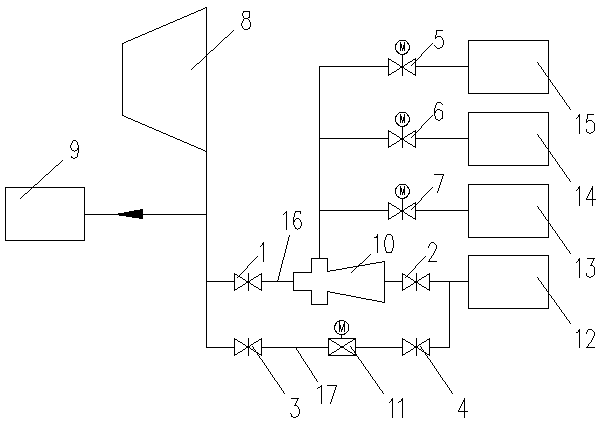
[0015] see figure 1 , the present invention includes No. 1 valve 1, No. 2 valve 2, No. 3 valve 3, No. 4 valve 4, No. 5 valve 5, No. 6 valve 6, No. 7 valve 7, back pressure steam turbine 8, external network heating device 9. Steam jet pump 10, regulating valve 11, deaerator 12, drain tank 13, drain expander 1, regular blowdown expander 15, main pipeline 16 and bypass pipeline 17.

[0016] The exhaust port of the back pressure steam turbine 8 is connected to the deaerator 12 through the main pipeline, and the first valve 1, the steam injection pump 10 and the second valve 2 are installed in sequence on the main pipeline 16. Wherein, both the inlet and the outlet of the steam jet pump 10 are connected with the main pi...


PUM


Abstract

The invention provides a recovery system and a recovery method of residual pressure and residual heat in a backpressure heat supply unit. The system and the method can reduce loss if water, heat and pressure energy, increase heat supply of the backpressure heat supply unit and eliminate a phenomenon of 'generating white smoke'. The system comprises a backpressure steam turbine, a deaerator, a drain tank, a drain flash tank, periodic blowdown flash tank, valves from No.1 to No.7, a steam jet pump, a main pipeline and a bypass pipeline. In normal operation, the No.3 valve and the No.4 valve areclosed, and other valves are opened; discharged steam of the backpressure steam turbine is conveyed into the steam jet pump to be used as working steam, thus, after the steam jet pump extracts the discharged steam in the periodic blowdown flash tank, the drain flash tank and the drain tank, pressure is reduced and the steam becomes medium pressure steam usable for the deaerator, and the medium pressure steam enters into the deaerator; if the steam jet pump goes wrong, the No.3 valve and the No.4 valve of a bypass line are opened, and the No.1 valve and the No.2 valve are closed, the system cancontinue working, and thus continuous running of the system is guaranteed.

Description

technical field [0001] The invention relates to a recovery system and recovery method for excess pressure and waste heat in a back pressure heating unit. Background technique [0002] 1. In the traditional back pressure heating unit, the back pressure exhaust steam pressure of the external network heating often cannot match the heating steam pressure of the deaerator. In order to meet the requirements of the external network heating, the heating steam of the deaerator It is often necessary to reduce pressure and temperature through throttling, which will inevitably cause waste of pressure energy due to throttling and decompression. [0003] 2. In the traditional back-pressure heating unit, it is necessary to set up expansion devices such as regular sewage expansion vessels, drainage expansion vessels, and drainage tanks. The exhaust steam of these devices often leads directly to the atmosphere, and often forms the phenomenon of "white smoke". This phenomenon not only easily...

Claims


Application Information

Patent Timeline
IPC IPC(8): F01K17/02F01K19/00F04F5/54F28D21/00
CPCF01K17/025F01K19/00F04F5/54F28D21/0014Y02B30/56
Inventor 毛刚金宇航朱佳斌周姣梁小丽吴俊芬徐雪莹王纯夏积恩戴佳栩寿恩广刘含文
Owner CHINA UNITED ENG
Learn More