A secondary booster pump for oilfield water injection

A technology of secondary pressurization and oil field water injection, which is applied in the direction of pumps, piston pumps, pump components, etc., and can solve problems such as high energy consumption, low system efficiency, and poor synchronization and coordination of solenoid valves

Active Publication Date: 2020-10-30
沈阳风正技术发展有限公司
View PDF10 Cites 1 Cited by
  • Summary
  • Abstract
  • Description
  • Claims
  • Application Information

AI Technical Summary

Problems solved by technology

[0008] One is to use the water pressure of the pipe network to drive the hydraulic pressure booster device. The disadvantage is that it needs to lay a special low-pressure return water pipeline; the disadvantage is that a large number of parts such as control valves need to be designed and processed by themselves. The lubricity of the water itself is poor, and the self-made parts are reliable. It is difficult to guarantee the performance, which will lead to poor practical applicability and difficult promotion
[0010] However, the existing drive booster devices still have shortcomings in the system design, such as not simple enough, low system efficiency, and large energy consumption.
For example, some solenoid valves (on-off valves) connected in series in the hydraulic control circuit are used to control the action of the booster device. Such a design has the disadvantages of large hydraulic shock and poor synchronization (or coordination) when the solenoid valve is opened.
There are also designs that use a throttle valve to control the action speed of the supercharging device. The way of throttling and speed regulation itself consumes energy and is not energy-saving.

Method used


Image

  • A secondary booster pump for oilfield water injection
  • A secondary booster pump for oilfield water injection
  • A secondary booster pump for oilfield water injection

Examples


Embodiment 1

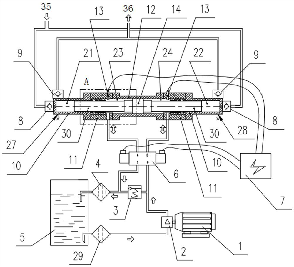
[0037] like figure 1 , figure 2 As mentioned above, the present invention is a secondary booster pump for oil field water injection, and a prime mover 1, a hydraulic pump 2, a safety valve 3, a hydraulic filter 4, a hydraulic oil tank 5, and a hydraulic reversing valve 6 constitute a hydraulic drive system. The output shaft end of the prime mover 1 is connected with the input shaft end of the hydraulic pump 2, the oil inlet of the hydraulic pump 2 is connected with one end of the filter 29, and the other end of the filter 29 is connected with a port of the hydraulic oil tank 5; the hydraulic pump 2 The outlet of the hydraulic reversing valve 6 is divided into two routes, one is connected to the oil inlet port of the hydraulic reversing valve 6, and the other is connected to the inlet of the safety valve 3; One end of the hydraulic filter 4 is connected with one of the ports of the hydraulic oil tank 5 .

[0038] The first working oil port of the hydraulic reversing valve 6 is...

Embodiment 2

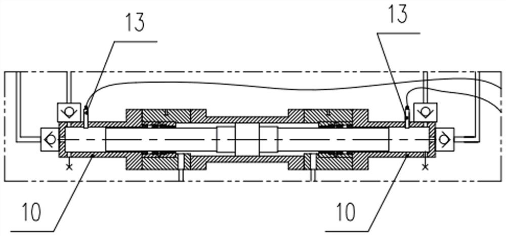
[0071] like image 3 As shown, its connection mode is basically the same as that of Embodiment 1, the difference is that

[0072] The position detection element 13 is installed on the hydraulic cylinder 10 .

Embodiment 3

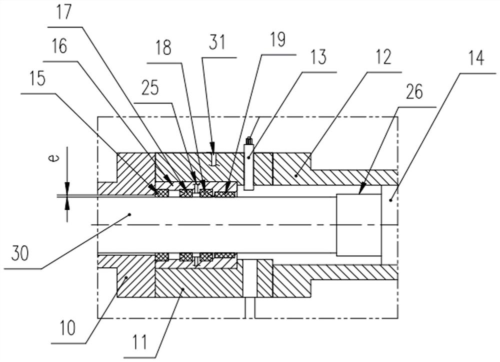
[0074] like Figure 4 As shown, its connection mode is basically consistent with Embodiment 1, 2, the difference is that, figure 2 The transition connecting body 11 and the guiding process element 16 are combined into an integral connecting body 20 of an integral structure.


PUM


Abstract

The invention discloses a secondary booster pump for oilfield water injection, and belongs to the technical field of petroleum water injection exploitation. The booster pump comprises a boosting system and a hydraulic driving system. The boosting system comprises a cylinder body, a piston body is arranged in the cylinder body, and the middle of the piston body closely fits the interior of the cylinder body; the left and right sides of the piston body are provided with plunger rods, and the left and right ends of the plunger rods and the interiors of the two ends of the cylinder body form isolated high-pressure water chambers; the portions, in the middles of the plunger rods on the left and right sides, of the interior of the cylinder body are provided with plugging devices, isolated hydraulic oil chambers are formed between the piston body and the plugging devices on the left and right sides, and the hydraulic oil chambers are connected with the hydraulic driving system; and the portions, at the ends of the high-pressure water chambers, of the two ends of the cylinder body are connected with a water supply network pipe through water inlet check valves, and the portions, at the upper parts of the high-pressure water chambers, of the two ends of the cylinder body are connected with a well through water outlet check valves. According to the booster pump, the hydraulic pressure ofan existing pipe network is utilized, the boosting system is used for supplementing pressure on the basis of the pressure, and then the final hydraulic pressure meets the injection requirement of thewell.

Description

technical field [0001] The invention belongs to the technical field of oil water injection and production, and in particular relates to a secondary booster pump for oil field water injection. Background technique [0002] Water injection production refers to the injection of water into the oil reservoir through special water injection wells in the process of oilfield development to maintain or restore the pressure of the oil layer, so that the oil reservoir has a strong driving force, so as to improve the production speed and recovery rate of the oil reservoir. The water injection system and its main process flow are water injection pump station → water injection pipe network → water distribution room → injection well. "Single-pipe multi-well water distribution process" is a method commonly used in domestic oil fields, that is, one or more large-displacement high-pressure water pumps are installed in the water injection pumping station (the capacity of the driving motor is u...

Claims


Application Information

Patent Timeline
Patent Type & Authority Patents(China)
IPC IPC(8): F04B9/113F04B53/14F04B53/16F04B49/00F15B21/041F15B13/02E21B43/20
CPCE21B43/20F04B9/1095F04B9/113F04B49/00F04B53/14F04B53/143F04B53/162F15B13/021F15B21/041
Inventor 刘航薛金瑞
Owner 沈阳风正技术发展有限公司
Why Eureka
Try Eureka