Novel micro aero-engine combustion chamber

A technology for aero-engines and combustion chambers, applied in the direction of combustion chambers, continuous combustion chambers, combustion methods, etc., can solve the problems of lack of fixing effect of engine combustion chambers, easily affected flame tube structure design, high requirements for evaporation tubes, etc., and achieve enhanced Oil circuit stability, high strength, and the effect of enhancing combustion efficiency

Inactive Publication Date: 2020-08-11
NORTHWESTERN POLYTECHNICAL UNIV
View PDF7 Cites 5 Cited by
  • Summary
  • Abstract
  • Description
  • Claims
  • Application Information

AI Technical Summary

Problems solved by technology

[0005] In addition to the high requirements for the evaporator tube, the current micro-engine combustion chamber lacks the fixing effect. Due to the strong vibration of the engine during the working process, the structure design of the flame tube in the combustion chamber is easily affected, resulting in poor stability. The current design of its fixing effect There are always certain problems, so the fixed action design of the micro-aero-engine combustion chamber also needs to be improved

Method used


Image

  • Novel micro aero-engine combustion chamber
  • Novel micro aero-engine combustion chamber
  • Novel micro aero-engine combustion chamber

Examples


Embodiment Construction

[0024] The present invention will be further described now in conjunction with accompanying drawing:

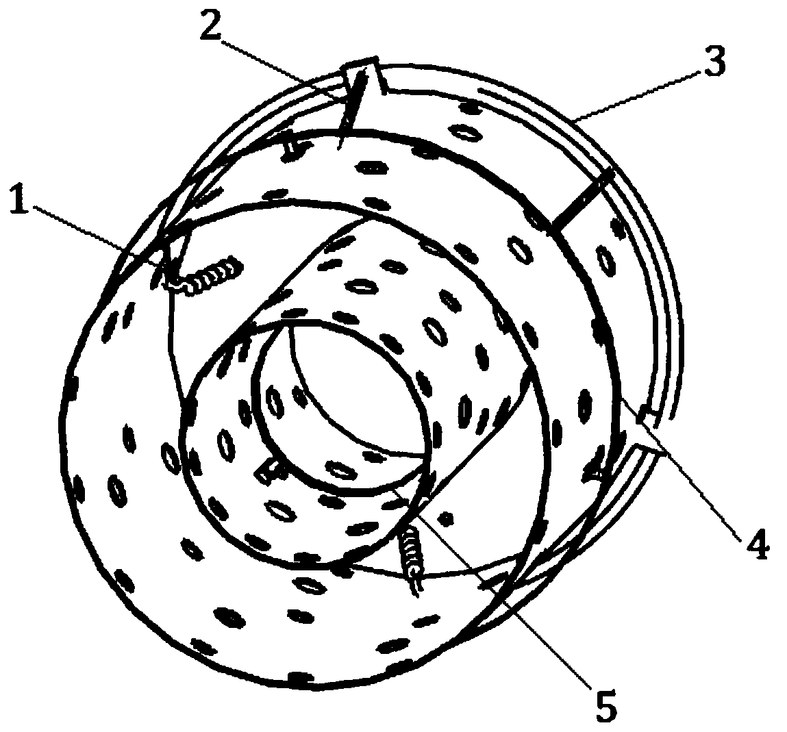
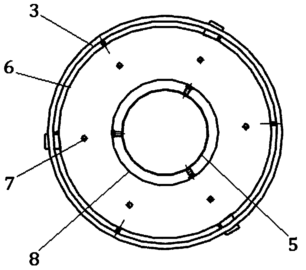
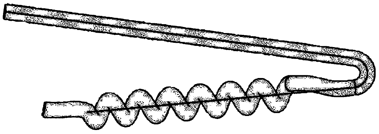
[0025] combine Figure 1-5 , The invention provides a technical scheme of a novel miniature aero-engine combustor. figure 1 It is the overall schematic diagram of the new micro-combustion chamber, figure 2 It is a view of the head structure of the new micro-combustion chamber, image 3 A schematic diagram of a spiral evaporator tube, Figure 4 A detailed drawing of the combustion chamber fixture, Figure 5 An enlarged schematic diagram of the porous medium wall of the flame cylinder.

[0026] To sum up the schematic diagram of the structure, on the one hand, when the combustion chamber is working, the fuel first flows in from the fuel main pipe 3, and flows into the flame tube evenly through the six fuel branch pipes 2. Full preheating is realized in the path, and the spiral structure can improve the stability of the evaporator tube to ensure that it is not deformed by ...


PUM


Abstract

The invention provides a novel micro aero-engine combustion chamber, and relates to the technical field of micro aero-engines. Based on the defects that an oil way structure of a traditional micro aero-engine combustion chamber is long in distance, an oil way is prone to deform due to external action and the like, the novel micro aero-engine combustion chamber adopts a spiral evaporation pipe structure, so that the oil way stability is enhanced, and the combustion efficiency is improved; based on the factors that the traditional micro aero-engine combustion chamber is poor in overall fixing effect, and the position of a flame tube is prone to be unstable under the high-temperature effect, the novel micro aero-engine combustion chamber adopts a flame tube fixing device structure so that theflame tube can be effectively fixed, and position deviation of the flame tube caused by vibration in the working process is prevented, and the flame tube can be prevented from being influenced by vibration during working; a double-layer wall surface structure of the flame tube is adopted, and the space between the wall surfaces is filled with porous media so that the effective damping effect canbe achieved; and meanwhile, the flame tube can be cooled to a certain degree, so that the wall surface cooling effect is achieved, and the service life of the wall surfaces of the flame tube is prolonged.

Description

technical field [0001] The invention belongs to the technical field of micro-aero-engines, and in particular relates to a novel micro-aero-engine combustion chamber. Background technique [0002] Since the emergence of the concept of micro-engine in the 1980s, the research on micro-engine and its related technologies has made great progress. With its unique advantages, micro-engine has attracted the attention of various countries and has great development potential. In recent years, the micro power system has become a research hotspot at home and abroad, among which the micro turbine engine is one of the most promising power, with the advantages of small size, light weight, large output energy, high density, high thrust-to-weight ratio, etc., and can also be used as a power generator The device has good development prospects and broad application prospects. [0003] The design of the micro-combustion chamber is the key link and the most important part of the micro-turbine e...

Claims


Application Information

Patent Timeline
Patent Type & Authority Applications(China)
IPC IPC(8): F23R3/32F23R3/42
CPCF23R3/32F23R3/42
Inventor 张群李小龙程祥旺胡凡
Owner NORTHWESTERN POLYTECHNICAL UNIV
Why Eureka
Try Eureka