
3D printer of wax part

A 3D printer and parts technology, which is applied to 3D object support structures, processing heating elements, and accessories for processing main materials. Effect

Pending Publication Date: 2020-08-14
QINGDAO HUANGHAI UNIV
View PDF0 Cites 1 Cited by
  • Summary
  • Abstract
  • Description
  • Claims
  • Application Information

AI Technical Summary

Problems solved by technology

[0007] In order to solve the technical problems of complex equipment and expensive consumables when 3D printers make waxy parts, the present invention provides a 3D printer for waxy parts. The specific technical scheme is as follows

Method used


Image

  • 3D printer of wax part
  • 3D printer of wax part
  • 3D printer of wax part

Examples


Embodiment 1

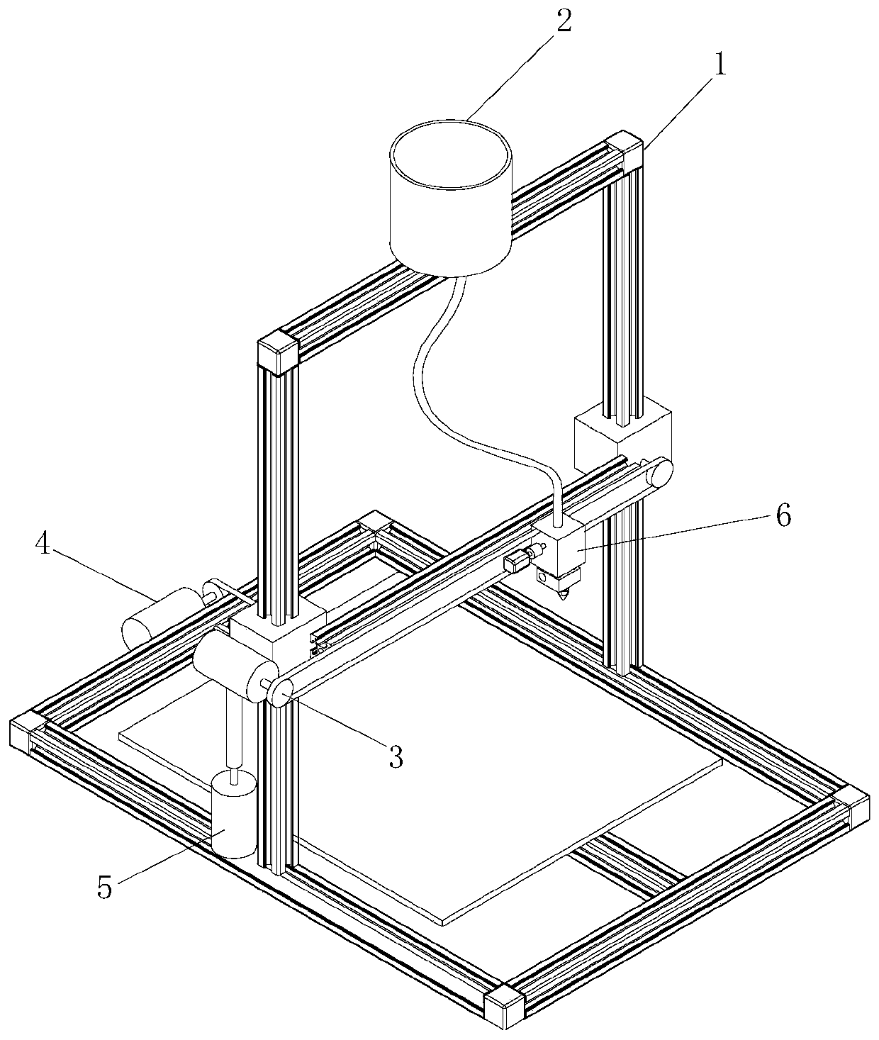
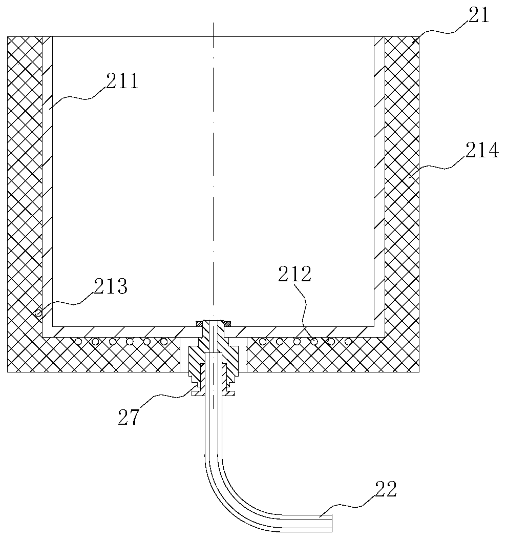
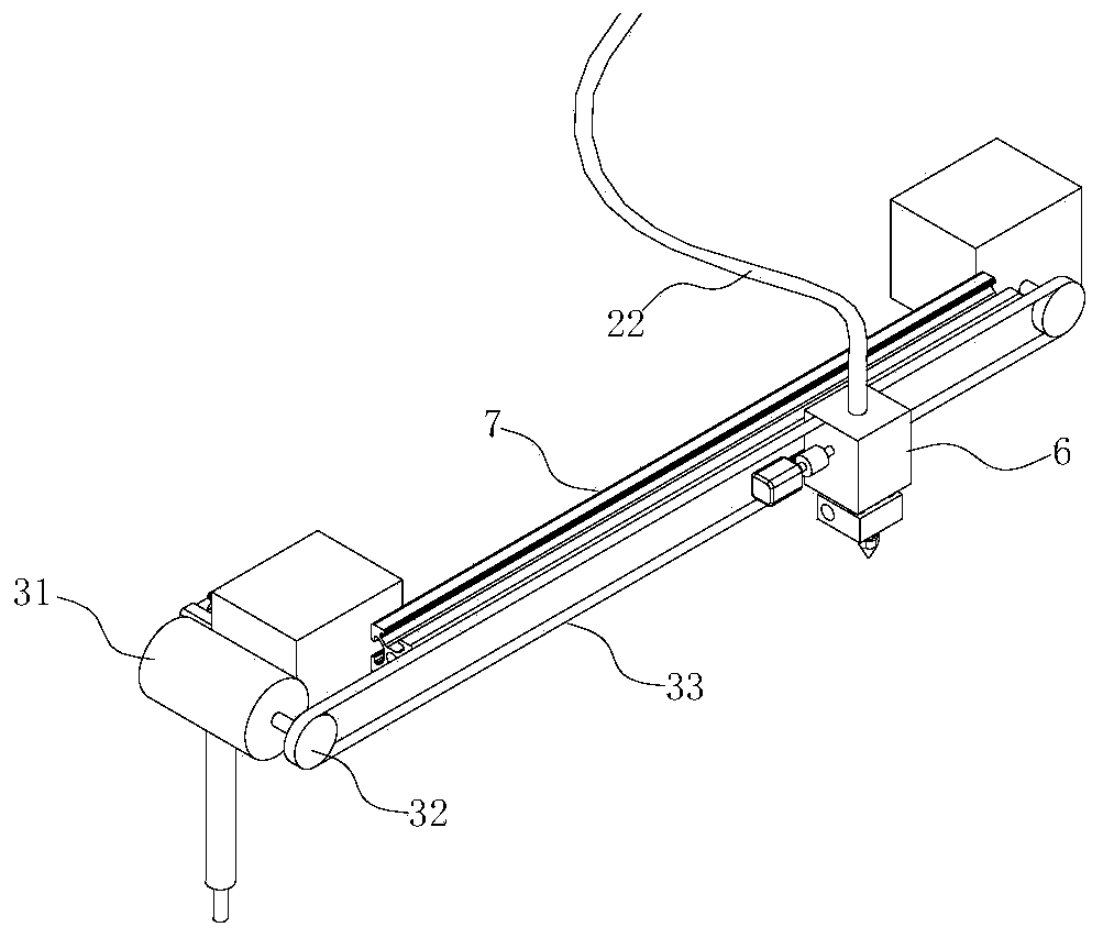
[0036] like Figure 1 to Figure 6 As shown, the 3D printer for wax parts in this embodiment has a frame, a filament extrusion system and a space motion system. Frame 1 is set on the outside of the wax parts 3D printer to form a frame structure. There is a printing bed 8 under the frame 1. The space above the printing bed 8 is the printing space. The printing carriage 6 can move freely in the printing space above the printing bed. , so as to complete the printing conveniently. The space motion system of the 3D printer is the same as the space motion system of the FDM three-dimensional printer. The space motion system has a first direction motion mechanism 3, a second direction motion mechanism 4, a third direction motion mechanism 5, and a printing cart 6. The printing cart 6 is on the beam. If set above, the printing carriage 6 can move freely in the printing space; wherein the first direction is the X-axis direction, the second direction is the Y-axis direction, and the thir...

Embodiment 2

[0043] like Figure 7 to Figure 12 As shown, this embodiment provides a 3D printer for wax parts, which has a frame, a consumable extrusion system and a space motion system. Frame 1 is set on the outside of the wax parts 3D printer to form a frame structure. The frame structure is columnar as a whole. There is a printing bed 8 under the frame 1. The printing bed 8 can be a circular flat structure. The printing trolley 6 is on the printing bed 8. Move freely in the printing space above. Specifically, the frame 1 can also be provided with three parallel columns, the columns are vertically arranged with the printing bed, and the columns are connected and fixed by connecting columns. The space motion system is a cylindrical coordinate space motion system. The space motion system has a first direction motion mechanism 3, a second direction motion mechanism 4, a third direction motion mechanism 5, and a printing carriage 6. The printing carriage 6 moves in the printing space. Wher...


PUM


Abstract

The invention provides a 3D printer of a wax part and relates to the technical field of additive manufacturing. The 3D printer structurally comprises a machine frame, a consumable extrusion system anda spatial motion system. The consumable extrusion system comprises a paraffin wax container, a wax liquid conveying pipe, a positive displacement pump, a heating block, an extrusion head and a cooling fan. The paraffin wax container can be fixed to the machine frame, the wax liquid conveying pipe is connected with the paraffin wax container and the positive displacement pump, an outlet of the positive displacement pump is connected with the heating block, and an outlet of the heating block is connected with the extrusion head. The spatial motion system comprises a first direction motion mechanism, a second direction motion mechanism, a third direction motion mechanism and a printing trolley. The positive displacement pump, the heating block, the extrusion head and the cooling fan are arranged on the printing trolley. The 3D printer uses industrial paraffin wax as a consumable and prints the wax part through a fused deposition modeling process. By the adoption of the 3D printer of thewax part, the cost of the printer can be greatly reduced, the structure of the printer is simplified as well, the price of the consumable is lowered, and the 3D printer is widely applied to the fieldssuch as investment casting and new product development.

Description

technical field [0001] The invention relates to the technical field of additive manufacturing, in particular to a 3D printer for making wax parts. Background technique [0002] 3D printing technology is a technology that directly drives 3D printers to quickly complete three-dimensional physical solid parts of any complex shape after the 3D CAD data model is processed by slicing software. It is also called Additive Manufacturing technology (Additive Manufacturing technology). 3D printing is the process of forming parts layer by layer on the printing bed (substrate) through special equipment. During the forming process of parts, the material is continuously increasing, so it is called additive manufacturing. Since 3D printing technology does not require complex processes of mold making, casting and forging, and machining, it has unique advantages in the field of product development of single-piece production. [0003] Currently, common 3D printer models include SLA, DLP, FDM,...

Claims


Application Information

Patent Timeline
Patent Type & Authority Applications(China)
IPC IPC(8): B29C64/20B29C64/255B29C64/295B29C64/118B29C64/30B29C64/386B33Y30/00B33Y50/00
CPCB29C64/118B29C64/20B29C64/255B29C64/295B29C64/30B29C64/386B33Y30/00B33Y50/00
Inventor 孙维丽杨东进葛伟伟宋爱利陈继涛刘纪新马玉华
Owner QINGDAO HUANGHAI UNIV
Learn More