
Cab hood structure, railway vehicle and production process

A preparation process and cab technology, applied in the field of vehicle engineering, can solve the problems of scrapped hood, high scrap rate, and difficult molding.

Pending Publication Date: 2020-08-14
北京天亿万赛轻量化材料有限公司
View PDF0 Cites 0 Cited by
  • Summary
  • Abstract
  • Description
  • Claims
  • Application Information

AI Technical Summary

Problems solved by technology

[0003] In the prior art, the driver's cab hood is one-piece injection molding. Since the depth of the hood cavity of the driver's cab hood is relatively large in the front and rear directions, there are problems in the molding process that the molding is difficult and the reject rate is high; After molding of the hood, if there is an injection defect at any position of the hood, the whole hood will be scrapped, resulting in high production cost of the hood

Method used


Image

  • Cab hood structure, railway vehicle and production process
  • Cab hood structure, railway vehicle and production process
  • Cab hood structure, railway vehicle and production process

Examples


Embodiment 1

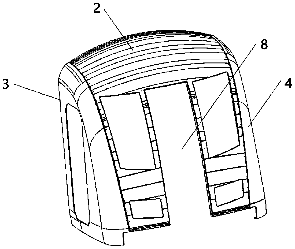
[0057] This embodiment provides a rail vehicle, for example, it can be a rail vehicle such as a subway or a high-speed rail, wherein the rail vehicle includes an underframe and a driver's cab hood structure, and the bottom of the driver's cab hood structure is installed on the underframe , and then installed on the track through the chassis.

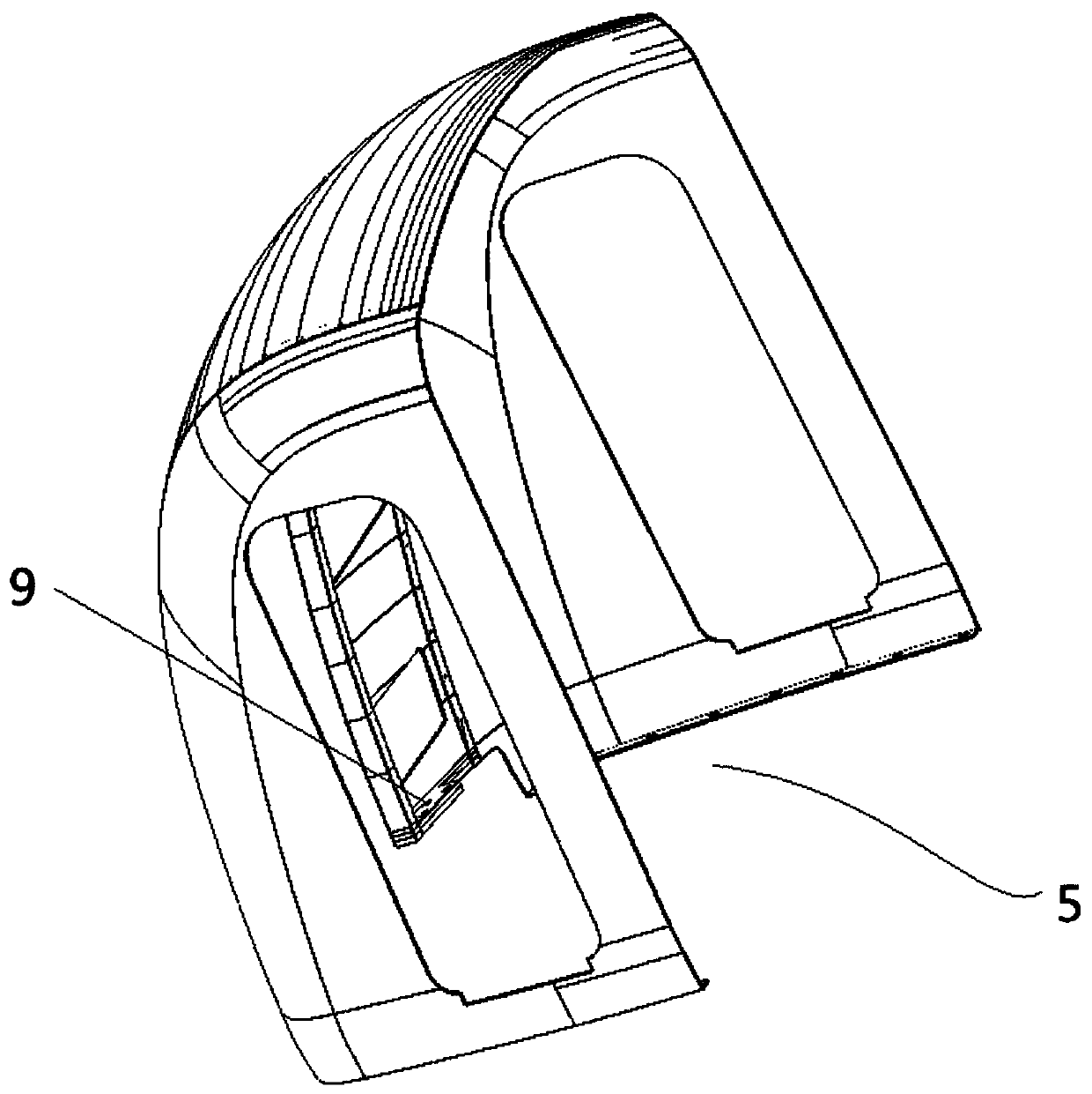
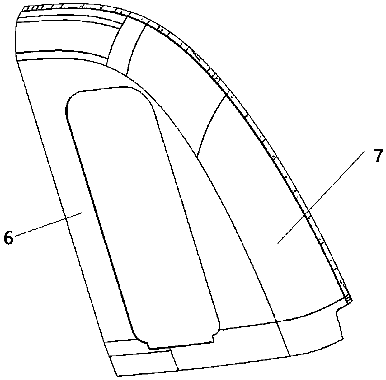
[0058] In this embodiment, the above-mentioned driver's cab hood structure includes at least two cover panels, and all the cover panels form the hood structure after being enclosed and fixed. Specifically, the cover panels can be set as a composite structure, which includes a body and At least one carbon fiber layer (not shown in the figure) and at least one toughening layer, the toughening layer and the carbon fiber layer are laid alternately, and then the resin body is filled in the holes of the carbon fiber layer and wrapped in all the alternate layers. Outside the carbon fiber layer and the toughening layer laid out, specifically, th...

Embodiment 2

[0065] This embodiment provides a preparation process for the structure of the driver's cab hood, which is used to prepare such as figure 1 In the driver's cab hood structure shown, each cover plate is formed first, which can be the above-mentioned main cover plate 2, left cover plate 3 and right cover plate 4, wherein the cover plate is a composite structure, specifically, aramid fiber fabric and The carbon fiber layers are laid alternately and are wrapped by the resin body to form a composite structure, in which the resin can be filled into the holes of the carbon fiber layers. The specific molding steps are as follows:

[0066] First of all, it is necessary to shape each cover plate, specifically, lay aramid fiber fabric and carbon fiber layer alternately on the inner wall surface of the lower mold, and secondly, clamp the lower mold and the upper mold so that the upper mold and the lower mold A cavity is formed between the upper carbon fiber layer and the aramid fiber fabr...


PUM


Abstract

The invention relates to the technical field of vehicle engineering, and particularly relates to a cab hood structure, a railway vehicle and a production process. The hood structure comprises at leasttwo hood plates, the hood plates are made of resin at least, any two adjacent hood plates are connected at least through an adhesive, and the adhesive is a high-molecular polymer adhesive; and a hoodis defined by all the hood plates, and the hood is provided with at least one hood cavity with an opening. In the cab hood structure, the hood structure is divided into at least two hood plates; thetwo hood plates are formed in a split manner; when the hood is fixed, the high-molecular polymer adhesive is used as the adhesive to bond and fix two adjacent hood plates; safety performance can reacha safety performance standard required when the cab hood is applied to the rail for fixed installation and actual use, and an effect that the safety performance is the same as that required when theintegrally-formed hood plate is applied to the rail for fixed installation and actual use is achieved.

Description

technical field [0001] The invention relates to the technical field of vehicle engineering, in particular to a driver's cab hood structure, a rail vehicle and a preparation process. Background technique [0002] In recent years, urban rail vehicles have attracted the attention of various countries for their fast, punctual, safe and convenient features, and have been vigorously promoted and developed. As an important core control part of urban rail vehicles, the design and production of the driver's cab is gradually becoming mature. After development and improvement, a complete structural system has gradually formed. To complete the driving work comfortably and effectively, the equipment layout in the cab must meet the relevant requirements of industry standards and combine the basic principles of ergonomics. [0003] In the prior art, the driver's cab hood is one-piece injection molding. Since the depth of the hood cavity of the driver's cab hood is relatively large in the ...

Claims


Application Information

Patent Timeline
IPC IPC(8): B61D17/00B61D19/02B29C69/00B29C65/48
CPCB29C65/48B29C69/00B61D17/00B61D17/005B61D19/023
Inventor 吴佩芳释加才让丁存光李发长于勇智刘家鑫肖云健惠鹏
Owner 北京天亿万赛轻量化材料有限公司
Learn More