
A high-efficiency utilization system of low-quality waste heat

A low-quality, waste heat technology, applied in the field of industrial waste heat utilization, can solve the problems of anti-oxidation, poor high temperature resistance, unstable gas work, inconvenient maintenance and other problems, and achieve the effect of not easy to break, simple structure and stable operation.

Active Publication Date: 2021-01-05
江苏科瑞德智控自动化科技有限公司 +1
View PDF9 Cites 0 Cited by
  • Summary
  • Abstract
  • Description
  • Claims
  • Application Information

AI Technical Summary

Problems solved by technology

The current waste heat recovery device uses water vapor as the working medium to recover low-quality waste heat, the heat exchange efficiency is low, and the use of water vapor also needs to consider corrosion problems
In addition, the low-quality waste heat contains flue gas and other mixed gases containing a lot of dust or particles. During the heat exchange process, these gases are easy to deposit in the heat exchanger pipes, which will cause pipe blockage for a long time, and it is inconvenient to repair and maintain
The document with the application number 201611085197.9 discloses a low-quality waste heat recovery power generation device, which uses a heat pipe steam generator, and the pipes go back and forth more, making it difficult to manufacture, and the pipes are easy to break, and have poor oxidation resistance and high temperature resistance; and the Roots power machine uses The most important thing is the air intake from a single air inlet, which may easily cause the problem of unstable gas work

Method used


Image

  • A high-efficiency utilization system of low-quality waste heat
  • A high-efficiency utilization system of low-quality waste heat
  • A high-efficiency utilization system of low-quality waste heat

Examples


Embodiment Construction

[0023] The present invention will be further described below in conjunction with the embodiments and accompanying drawings. The specific embodiments are only used to further describe the present invention in detail, and do not limit the protection scope of the claims of the present application.

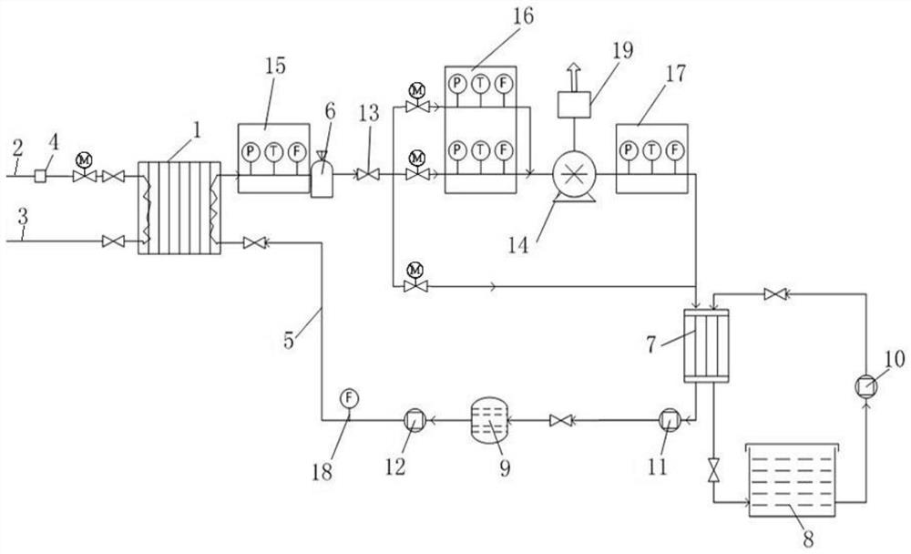
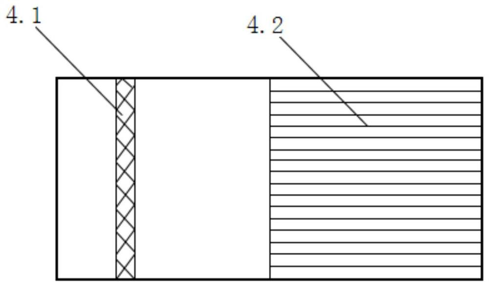
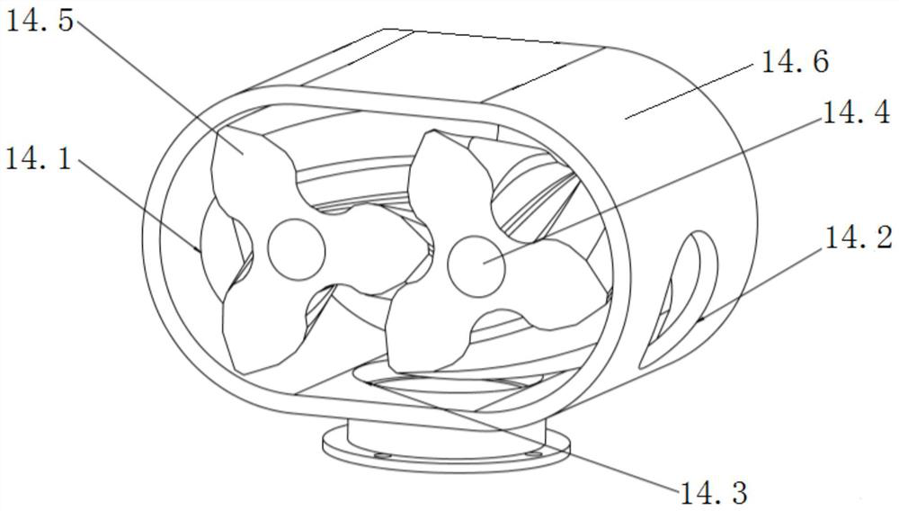
[0024] The present invention provides a system for high-efficiency utilization of low-quality waste heat (referred to as the system, see Figure 1-3 ), characterized in that the system includes a waste heat recovery system and a circulation system;

[0025] The waste heat recovery system includes an evaporator 1, a waste heat inlet pipe 2, a waste heat outlet pipe 3 and a filter device 4; one end of the waste heat inlet pipe 2 is a waste heat inlet for the entry of low-quality waste heat gas, and the other end is connected with The air inlet of the evaporator 1 is connected; the waste heat air inlet pipe 2 is provided with a filter device 4, a stop valve and an electric valve, and th...


PUM


Abstract

The invention discloses a system for high-efficiency utilization of low-quality waste heat. The system for the high-efficiency utilization of the low-quality waste heat comprises a waste heat recoverysystem and a circulating system, wherein the waste heat recovery system comprises an evaporator, a waste heat inlet pipe, a waste heat outlet pipe and a filtering device; and the circulating system comprises an organic working medium pipeline, a gas storage tank, a condenser, a liquid storage tank, a condensate pump, a liquid replenishing pump, flow dividing control valves, a Roots power machine,a gas storage tank sensor group, a gas inlet sensor group, a gas outlet sensor group and liquid replenishing flowmeters. According to the system for the high-efficiency utilization of the low-qualitywaste heat, low-quality waste heat gas is used as a heat source, an organic working medium is used as a circulating working medium, the waste heat recovery system enables the liquid organic working medium to absorb heat from the waste heat gas and convert the heat into a gaseous state, the steam of the organic working medium enters the Roots power machine to push the Roots power machine to do work, heat energy is converted into mechanical energy, and then the steam of the organic working medium is condensed into the liquid state through the condenser and is continuously recycled. The system for the high-efficiency utilization of the low-quality waste heat achieves recycling of the low-quality waste heat, and is simple in structure, high in energy utilization rate and high in heat conversion efficiency.

Description

technical field [0001] The invention relates to the field of industrial waste heat utilization, in particular to a high-efficiency utilization system of low-quality waste heat. Background technique [0002] Industrial waste heat is a conventional recyclable energy with the widest distribution and the greatest application potential in industrial production. In industrial production, there are a large number of waste heat resources, including flue gas, steam and hot water, etc. These resources are widely distributed and commonly found in steel, petroleum, non-ferrous metals, chemical industry, light industry, building materials and other industries. The generation of waste heat resources is due to the consumption of coal, oil and various combustible gas emissions in the process of industrial production, which belongs to secondary energy. [0003] In the current industrial production process, a large amount of industrial waste heat energy is released into the environment in th...

Claims


Application Information

Patent Timeline
Patent Type & Authority Patents(China)
IPC IPC(8): F01K27/00F01K25/08F01C1/12F01C13/00F01C21/10B01D50/00
CPCB01D50/00F01C1/126F01C13/00F01C21/104F01K25/08F01K27/00
Inventor 肖艳军张亚盟周围刘伟玲彭凯
Owner 江苏科瑞德智控自动化科技有限公司
Learn More