Ultrathin vapor chamber with separated gas and liquid channels

A technology of gas-liquid channels and vapor chambers, applied in electrical components, heat exchange equipment, indirect heat exchangers, etc., can solve the problems of large gas-liquid flow resistance, large contact area, and increased heat transfer resistance of steam chambers. Achieve the effects of reducing flow resistance, reducing heat transfer resistance, and enhancing hydrophilicity

Pending Publication Date: 2020-08-14
WUXI JONES TECH +3
View PDF0 Cites 5 Cited by
  • Summary
  • Abstract
  • Description
  • Claims
  • Application Information

AI Technical Summary

Problems solved by technology

[0003] Studies have shown that when the thickness is below the critical thickness of 0.3mm, as the thickness further decreases, the heat transfer resistance of the steam chamber will increase rapidly, causing the overall heat transfer performance of the vapor chamber to decline
For the existing ultra-thin vapor chamber below 0.3mm, the space is extremely limited, and there is a problem of insufficient thickness of the steam chamber, and the spatial distribution of the capillary core and the steam chamber is separated by upper and lower layers. For example, the upper space of the vapor chamber is a steam channel, and the lower layer The space is the channel of the working fluid. This method of dividing the upper and lower layers further reduces the thickness of the steam chamber, and the vapor-liquid interface is equivalent to the radial area of ​​the entire vapor chamber, with a large contact area and large gas-liquid flow resistance.

Method used


Image

  • Ultrathin vapor chamber with separated gas and liquid channels
  • Ultrathin vapor chamber with separated gas and liquid channels
  • Ultrathin vapor chamber with separated gas and liquid channels

Examples


Embodiment 1

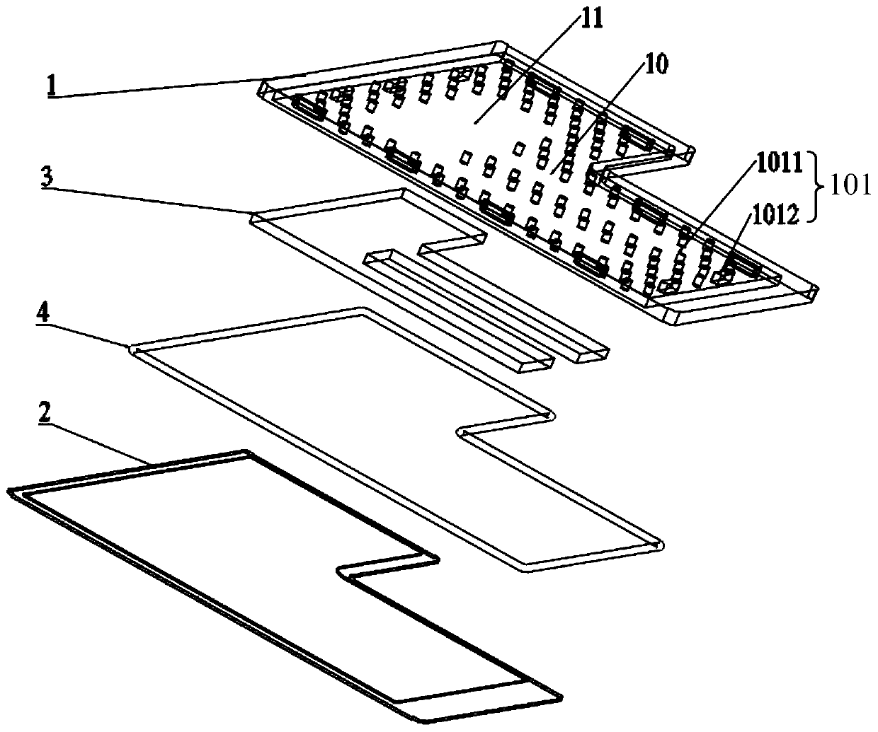
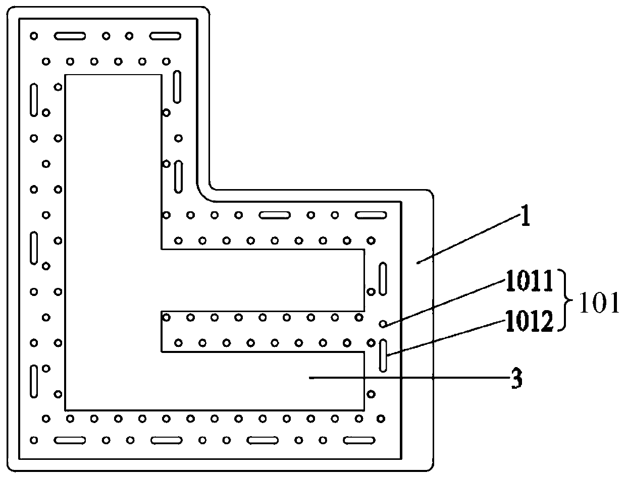
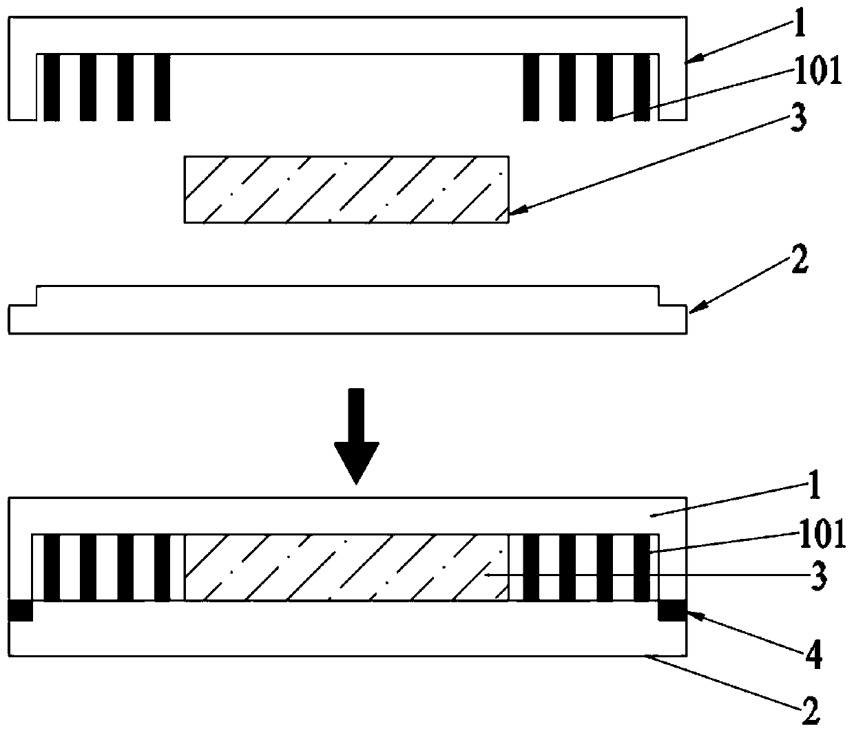
[0030] like Figure 1-2 As shown, an ultra-thin vapor chamber with separated gas-liquid channels includes a cover plate 1 and a bottom plate 2. The periphery of the cover plate 1 and the bottom plate 2 are sealed and connected to form a sealed working medium cavity. The sealed working medium cavity is in a vacuum state. The inside is filled with liquid working medium water, and the inner surface of the cover plate 1 is concave, including a first area 10 and a second area 11, wherein the first area 10 is provided with regularly arranged support columns 101, and the second area 11 is not provided The support column 101 is used to place the foamed copper liquid-absorbing core 3, the upper surface of the foamed copper liquid-absorbing core 3 is closely attached to the lower surface of the cover plate 1, and the lower surface of the foamed copper liquid-absorbing core 3 and the upper surface of the bottom plate 2 Surface fits snugly.

[0031] The wall thickness of the cover plate ...

Embodiment 2

[0038] like Figure 4-5 As shown, an ultra-thin vapor chamber with separated gas-liquid channels includes a cover plate 1 and a bottom plate 2. The periphery of the cover plate 1 and the bottom plate 2 are sealed and connected to form a sealed working medium cavity. The sealed working medium cavity is in a vacuum state. The inside is filled with liquid working medium water, and the inner surface of the cover plate 1 is concave, including a first area 10 and a second area 11, wherein the first area 10 is provided with regularly arranged support columns 101, and the second area 11 is not provided The support column 101 is used to place the foamed copper liquid-absorbing core 3, the upper surface of the foamed copper liquid-absorbing core 3 is closely attached to the lower surface of the cover plate 1, and the lower surface of the foamed copper liquid-absorbing core 3 and the upper surface of the bottom plate 2 Surface fits snugly.

[0039] The wall thickness of the cover plate ...


PUM

PropertyMeasurementUnit
thicknessaaaaaaaaaa
thicknessaaaaaaaaaa
thicknessaaaaaaaaaa

Abstract

The invention relates to a vapor chamber, in particular to an ultrathin vapor chamber with separated gas and liquid channels. The ultrathin vapor chamber with the separated gas and liquid channels comprises a cover plate and a bottom plate, wherein the periphery of the cover plate and the periphery of the bottom plate are hermetically connected to form a sealed working medium cavity; the sealed working medium cavity is in a vacuum state and is filled with a liquid working medium; the inner surface of the cover plate is a concave surface and comprises a first area and a second area; the first area is provided with supporting columns arranged regularly; the second area is not provided with supporting columns and is used for accommodating a foamy copper liquid absorbing core; the upper surface of the foamy copper liquid absorbing core is tightly attached to the lower surface of the cover plate; and the lower surface of the foamy copper liquid absorbing core is tightly attached to the upper surface of the bottom plate. The thickness of the ultrathin vapor chamber is 0.20-0.30 mm; a gap between the supporting columns on the inner side of the cover plate is a steam channel; the foamy copper liquid absorbing core is a working medium channel; and the steam channel and the working medium channel are independent of each other, so that the gas-liquid flow resistance can be effectively reduced, and the problem of local high heat flow heat dissipation of a microelectronic device in a limited space is solved.

Description

technical field [0001] The invention relates to a soaking plate, in particular to an ultra-thin soaking plate with separated gas-liquid channels. Background technique [0002] With the advancement of 5G network construction, the functions of 5G terminal equipment are more diversified, and chips need to cope with complex environmental conditions, and their high-speed operation will cause high heat problems. When meeting the requirements of high integration, lightness and space utilization of terminal equipment at the same time, it is necessary to consider the use of ultra-thin vapor chambers. Due to the fine and changeable internal structure of the vapor chamber and the complex phase change heat transfer mechanism, there are many factors that affect the heat transfer performance. With the development of vapor chamber towards ultra-thin trend, it is necessary to comprehensively consider various design problems. [0003] Studies have shown that when the thickness is below the...

Claims


Application Information

Patent Timeline
Patent Type & Authority Applications(China)
IPC IPC(8): F28D15/04F28F21/08H01L23/427
CPCF28D15/0233F28D15/046F28F21/081F28F21/089H01L23/427
Inventor 陈曲吴晓宁唐文军胡循亮唐黎何阳
Owner WUXI JONES TECH
Why Eureka
Try Eureka