C-band and X-band double-frequency controllable compact high-power microwave device

A high-power microwave and microwave device technology, applied in the field of C, can solve the problems of strong guiding magnetic field, large volume, high energy consumption, etc., and achieve the effect of reducing energy demand, reducing volume, and simple structure size

Active Publication Date: 2020-08-14
INST OF APPLIED ELECTRONICS CHINA ACAD OF ENG PHYSICS
View PDF3 Cites 0 Cited by
  • Summary
  • Abstract
  • Description
  • Claims
  • Application Information

AI Technical Summary

Problems solved by technology

In the existing high-power microwave sources, high-impedance devices have high beam conversion efficiency, but generally require a strong guiding magnetic field, especially when the microwave source operates at a repetition rate, a bulky, high-energy-consuming magnet system

Method used


Image

  • C-band and X-band double-frequency controllable compact high-power microwave device
  • C-band and X-band double-frequency controllable compact high-power microwave device

Examples


Embodiment 1

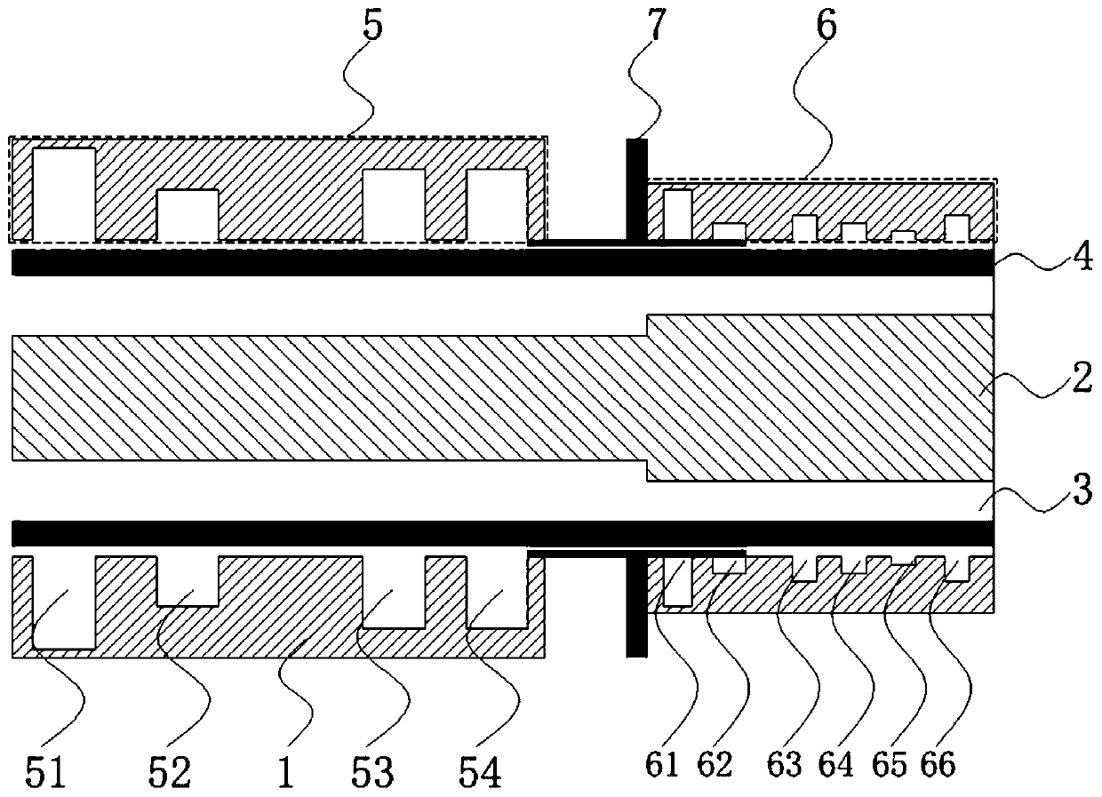
[0038] Such as figure 1 As shown, a C, X-band dual-frequency controllable compact high-power microwave device of this embodiment includes a circular waveguide outer cylinder, an inner conductor coaxial with the circular waveguide outer cylinder, the inner conductor and the circular waveguide outer cylinder A vacuum electron beam transmission channel is formed between the cylinders, and the annular electron beam is transmitted in the electron beam transmission channel;

[0039] The microwave device is sequentially provided with a C-band slow-wave structure and an X-band slow-wave structure including an inner conductor, and an axially movable metal circular waveguide is arranged between the C-band slow-wave structure and the X-band slow-wave structure. The outer diameter of the circular waveguide is the same as the inner diameter of the microwave device;

[0040] The ratio of the total axial length of the C-band slow-wave structure to the C-band radiation wavelength is 1.6, the...

Embodiment 2

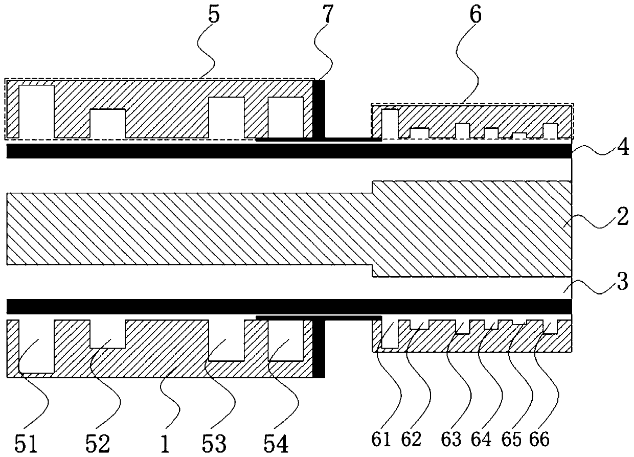
[0051] Such as figure 2 As mentioned above, the difference between this embodiment and Embodiment 1 is: in the embodiment, the vacuum degree in the microwave device is processed to the order of milliPascal by using a vacuum obtaining device, and the fourth cavity of the C-band slow wave structure is controlled by the metal circular waveguide body. A high voltage of 380kV is applied between the cathode and the anode, and the cathode emits a ring-shaped electron beam with an inner and outer diameter of 60mm and 70mm, respectively, and a beam intensity of 6kA. The ring-shaped electron beam is transmitted into the device under the guidance of a 0.63T axial magnetic field, and the electron beam transfers energy to the microwave field, generating high-power microwaves with a frequency of 8 GHz within one pulse.

[0052] In summary, the use of a C, X-band dual-frequency controllable compact high-power microwave device of the present invention can greatly reduce the volume and weigh...


PUM

PropertyMeasurementUnit
diameteraaaaaaaaaa
lengthaaaaaaaaaa
diameteraaaaaaaaaa

Abstract

The invention discloses a C-band and X-band double-frequency controllable compact high-power microwave device. The microwave device comprises aperiodic C-band and X-band slow-wave structures which aresequentially arranged and comprise coaxial inner conductors, a metal circular waveguide capable of moving axially is arranged between the C-band slow-wave structure and the X-band slow-wave structure, and part of the cavity of the C-band slow-wave structure or the X-band slow-wave structure can be directionally covered by controlling the axial position of the metal circular waveguide; the ratio of the total axial length of the C-band slow-wave structure to the C-band radiation wavelength is 1.6, the ratio of the total axial length of the X-band slow-wave structure to the X-band radiation wavelength is 1.97, and the inner diameter of the microwave device is 76 mm. Annular electron beams with the voltage of 380kV, the current of 6kA, the inner diameter of 60mm and the outer diameter of 70mmare transmitted in the microwave device under the guidance of a 0.63 T magnetic field, and 4GHz or 8GHz high-power microwaves are generated through controllable radiation. By adopting the C-band andX-band double-frequency controllable compact high-power microwave device provided by the invention, radiation can be controlled to generate 4GHz or 8GHz high-power microwaves.

Description

technical field [0001] The invention relates to a C, X band dual-frequency controllable compact high-power microwave device, which belongs to the technical field of high-power microwave devices. Background technique [0002] High-power microwave generally refers to electromagnetic waves with peak power above 100MW and operating frequency in the range of 1-300GHz. With the development of high-power microwave research, higher and higher requirements are put forward for the radiation performance of high-power microwave source systems. [0003] The axial O-shaped high-power microwave device is a kind of high-power microwave device that is widely used due to the easy guidance of the electron beam brought by the structure and the variable combination of the structure. At present, the radiation generation of axial O-type high-power microwave devices generally requires a longer slow-wave structure to achieve synchronization of the phase velocity of the electron beam and the microwa...

Claims


Application Information

Patent Timeline
Patent Type & Authority Applications(China)
IPC IPC(8): H01J23/24H01J23/04H01J25/34
CPCH01J23/24H01J23/04H01J25/34H01J2223/24H01J2223/04H01J2225/34
Inventor 丁恩燕张运俭谭杰康强向飞金晖胡进光王冬杨周炳陆巍张北镇安海狮
Owner INST OF APPLIED ELECTRONICS CHINA ACAD OF ENG PHYSICS
Why Eureka
Try Eureka