Battery cap counting machine

A technology of capping machine and battery, applied in primary batteries, equipment for manufacturing primary batteries, manufacturing of secondary batteries, etc., can solve the problem of inconsistent directions of battery tabs, inconsistent contact area between battery tabs and battery caps, and impact on batteries. The welding quality and welding success rate between the tab and the battery cover can achieve the effect of realizing fully automatic operation, improving production efficiency and improving the quality of welding.

Inactive Publication Date: 2020-08-14
HUIZHOU DUOKEDA TECH
View PDF7 Cites 0 Cited by
  • Summary
  • Abstract
  • Description
  • Claims
  • Application Information

AI Technical Summary

Problems solved by technology

[0002] In the production process of cylindrical batteries, one of the procedures needs to weld the battery lugs and caps of the semi-finished batteries that have been welded and grooved. The existing welding equipment is usually equipped with battery conveyor belts and battery cover conveyor belts. , and welding is carried out at the intersection of the two with a welding torch. When the battery to be welded is transferred from the source material to the welding conveyor belt, it is usually transferred by a manipulator and a clamp. Various factors, such as the looseness or vibration of the fixture, the offset of the battery due to external factors when the material is supplied, etc., make the direction of the tabs of the batteries on the conveyor belt inconsistent, resulting in the contact between the tabs of each battery and the battery cover during welding. The area is inconsistent, which affects the welding quality and welding success rate of the battery tab and the battery cover

Method used


Image

  • Battery cap counting machine
  • Battery cap counting machine
  • Battery cap counting machine

Examples


Embodiment Construction

[0031] In order to facilitate the understanding of those skilled in the art, the present invention will be further described in detail below in conjunction with specific embodiments and accompanying drawings.

[0032] Please refer to Figure 1-Figure 12 , a preferred embodiment of the present invention is.

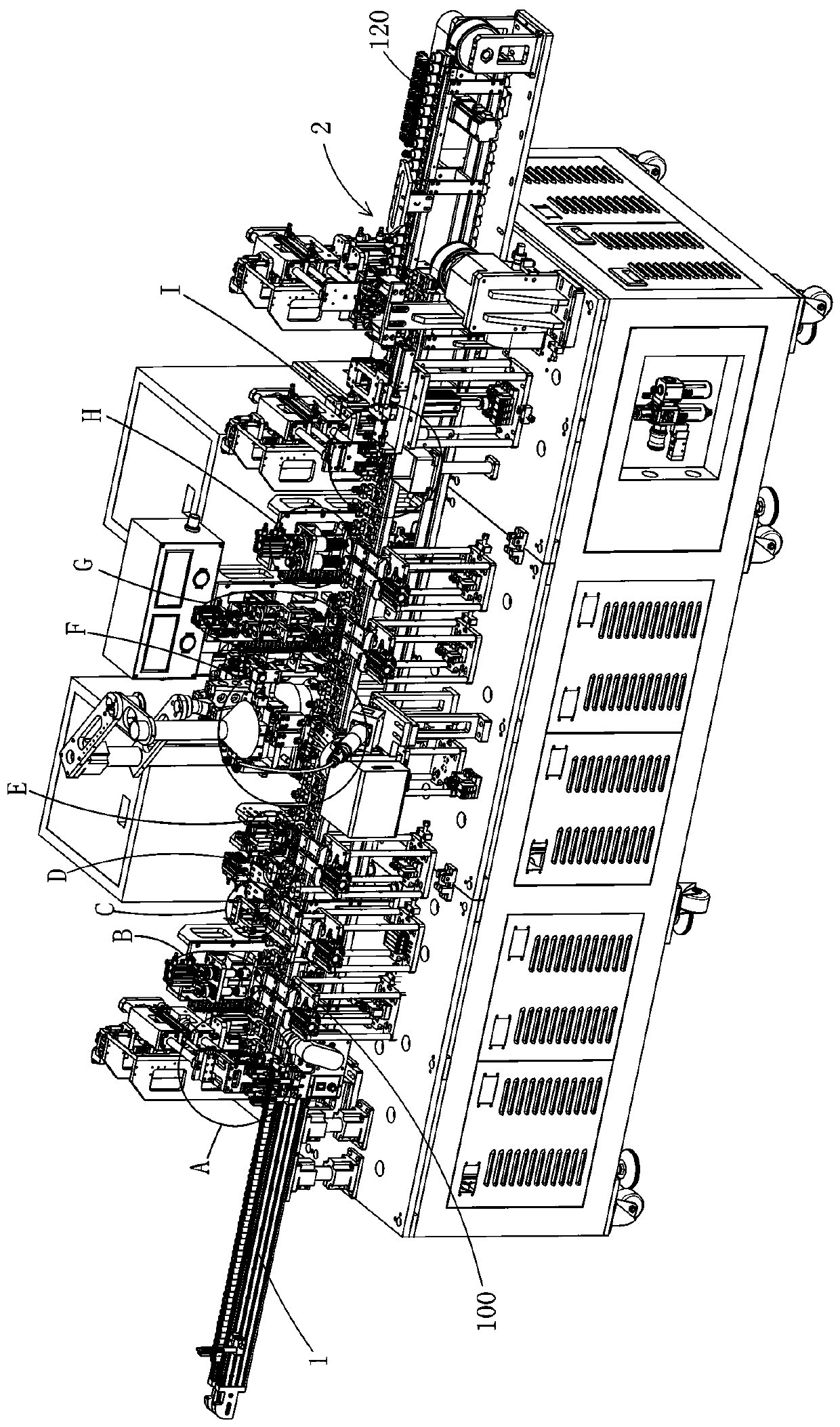
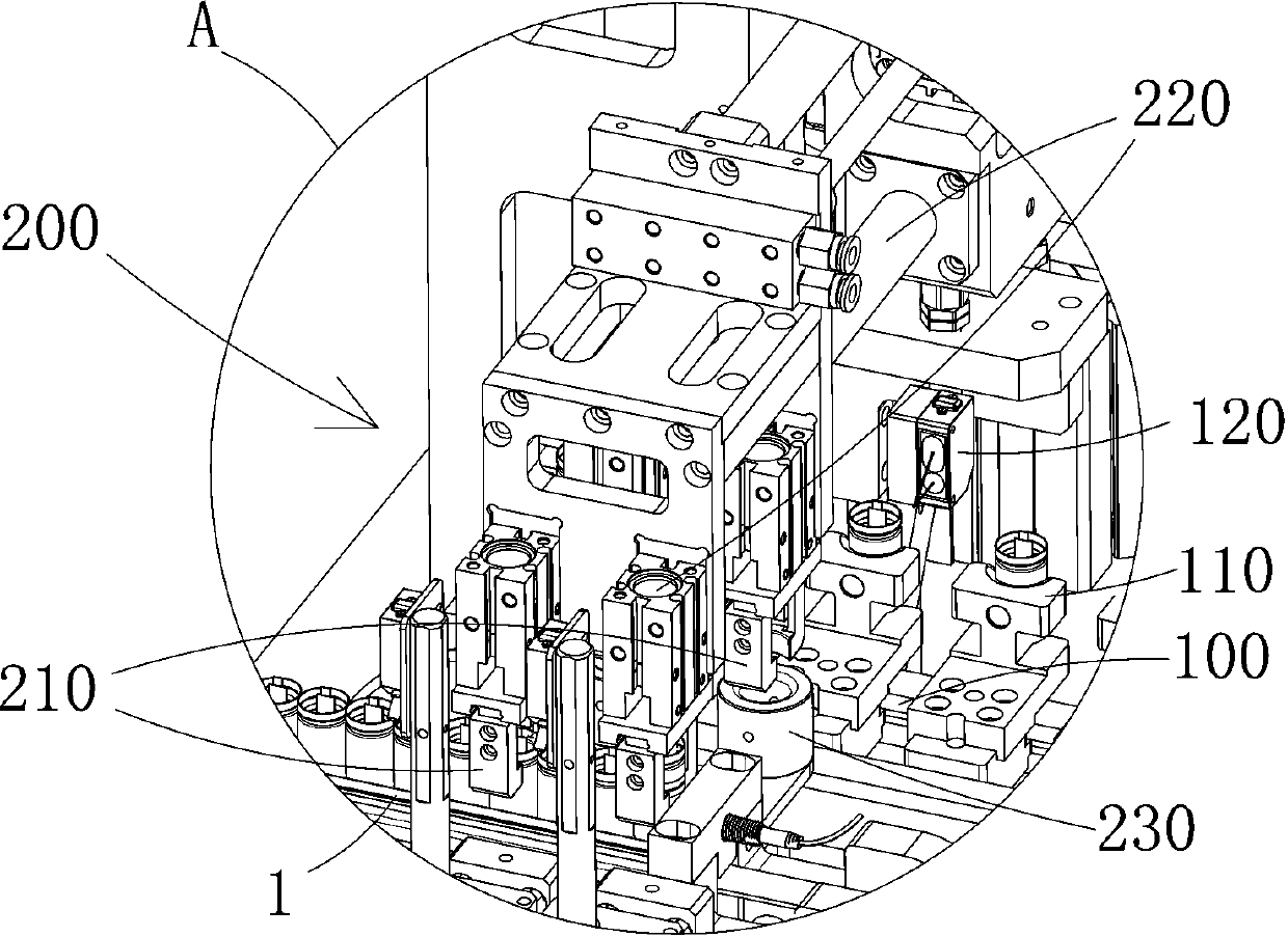
[0033] Please refer to figure 1 , a battery capping machine, including a conveyor belt 100 for transporting semi-finished batteries, the conveyor belt 100 is provided with battery slots 110, and the battery slots 110 are multiple and evenly distributed on the conveyor belt 100; and along the conveyor belt 100 conveying directions are distributed sequentially: the battery feeding mechanism 200 for transferring semi-finished batteries to the conveyor belt 100; the tab adjustment mechanism 400 for adjusting the direction of the tabs of the semi-finished batteries so that Straight lug bending, making it inclined tab bending mechanism 600; and a welding cap mechanism, the wel...


PUM


Abstract

The invention relates to a battery cap counting machine. The battery cap counting machine comprises a conveying belt for conveying semi-finished batteries, and a battery feeding mechanism, a tab adjusting mechanism, a tab bending mechanism, a cap welding mechanism, a quality detection mechanism, a defective battery discharging mechanism and a line transferring mechanism distributed successively along the conveying direction of the conveying belt. The battery feeding mechanism is used for transferring semi-finished batteries to the conveying belt; the tab adjusting mechanism is used for adjusting the tab direction of the semi-finished battery; the tab bending mechanism is used for bending a vertical tab; the quality detection mechanism is used for detecting the quality after welding, the defective battery discharging mechanism is used for discharging unqualified welded semi-finished batteries, and the line transferring mechanism is used for transferring the batteries which are welded completely and have qualified quality to a conveying line of the next procedure. Through tight connection and cooperation of the mechanisms, welding of a battery to a battery cover is effectively and reliably completed, meanwhile, full-automatic operation of welding is achieved, and the production efficiency of the battery is greatly improved.

Description

technical field [0001] The invention relates to the technical field of battery production equipment, in particular to a battery capping machine. Background technique [0002] In the production process of cylindrical batteries, one of the procedures needs to weld the battery lugs and caps of the semi-finished batteries that have been welded and grooved. The existing welding equipment is usually equipped with battery conveyor belts and battery cover conveyor belts. , and welding is carried out at the intersection of the two with a welding torch. When the battery to be welded is transferred from the source material to the welding conveyor belt, it is usually transferred by a manipulator and a clamp. Various factors, such as the looseness or vibration of the fixture, the offset of the battery due to external factors when the material is supplied, etc., make the direction of the tabs of the batteries on the conveyor belt inconsistent, resulting in the contact between the tabs of ...

Claims


Application Information

Patent Timeline
IPC IPC(8): H01M10/04H01M6/00
CPCH01M6/005H01M10/0422Y02E60/10Y02P70/50
Inventor 吴家军吴操
Owner HUIZHOU DUOKEDA TECH
Why Eureka
Try Eureka