
Flue gas low-temperature efficient desulfurization and denitrification device and method

A desulfurization, denitrification, and flue gas technology, which is applied in separation methods, chemical instruments and methods, gas treatment, etc., can solve problems such as increasing costs, reducing desulfurization and denitrification efficiency, and failing to meet the requirements of coking industry emission standards.

Inactive Publication Date: 2020-08-18
江苏峰峰鸿运环保科技发展有限公司
View PDF6 Cites 2 Cited by
  • Summary
  • Abstract
  • Description
  • Claims
  • Application Information

AI Technical Summary

Problems solved by technology

[0002] The treatment process of nitrogen oxides in the electric power, cement, glass and other industries is quite mature, but the temperature of the coke oven flue gas discharged from the coking plant is relatively low, and the NO X , SO 2 The content is relatively high. If the traditional denitrification process is adopted, it must be affected by the low flue gas temperature, SO 2 Restricted by factors such as high content, it cannot meet the NO requirements of the coking industry X Emission Standard Requirements
However, in order to reduce SO in the current technical means 2 The impact on the denitrification efficiency of low-temperature flue gas, the traditional desulfurization process is pre-installed in the denitrification process, and ammonia gas needs to be provided separately, which reduces the desulfurization and denitrification efficiency and increases the cost

Method used


Image

  • Flue gas low-temperature efficient desulfurization and denitrification device and method
  • Flue gas low-temperature efficient desulfurization and denitrification device and method
  • Flue gas low-temperature efficient desulfurization and denitrification device and method

Examples


Embodiment Construction

[0028] Embodiments of the present invention are described in detail below, examples of which are shown in the drawings, wherein the same or similar reference numerals designate the same or similar elements or elements having the same or similar functions throughout. The embodiments described below by referring to the figures are exemplary and are intended to explain the present invention and should not be construed as limiting the present invention.

[0029] In describing the present invention, it should be understood that the terms "length", "width", "upper", "lower", "front", "rear", "left", "right", "vertical", The orientation or positional relationship indicated by "horizontal", "top", "bottom", "inner", "outer", etc. are based on the orientation or positional relationship shown in the drawings, and are only for the convenience of describing the present invention and simplifying the description, rather than Nothing indicating or implying that a referenced device or element...


PUM


Abstract

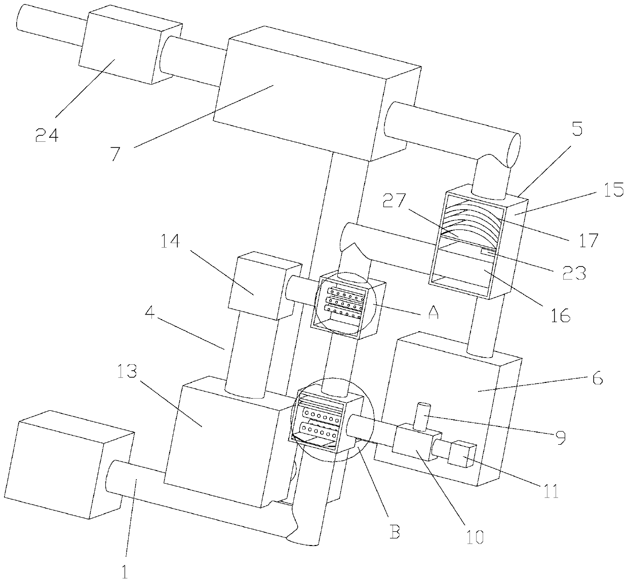
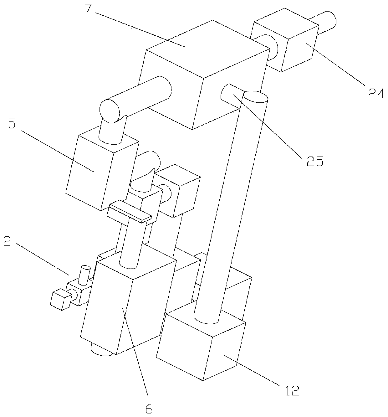
The invention discloses a flue gas low-temperature efficient desulfurization and denitrification device and method. The flue gas low-temperature efficient desulfurization and denitrification device comprises a flue gas exhaust pipe, a desulfurization system, a mixer, an ammonia production system, a denitrification system, a recovery system and an ammonia production tank; firstly, a fluidized desulfurizing agent is sprayed out through nanopores in a powder spraying pipeline by utilizing a compressed air assembly, is fully mixed and filtered with flue gas introduced by the flue gas exhaust pipein a mixing filter, then is introduced into a mixer, and is fully mixed with heated and dried ammonia gas; the mixed gas passes through an active coke layer to adsorb sulfur dioxide gas, and desulfurization treatment is carried out; and secondly, the mixed gas penetrates through a plurality of catalyst layers to be subjected to denitrification reaction, impurities obtained by filtering the flue gas and the active coke layer are recycled by utilizing a recycling system, and meanwhile, the gas subjected to denitrification reaction is discharged into the atmosphere through the ammonia productiontank, so that efficient desulfurization and denitrification can be realized, and the cost is reduced.

Description

technical field [0001] The invention relates to the technical field of flue gas harmless treatment, in particular to a device and method for low-temperature and high-efficiency desulfurization and denitrification of flue gas. Background technique [0002] The treatment process of nitrogen oxides in the electric power, cement, glass and other industries is quite mature, but the temperature of the coke oven flue gas discharged from the coking plant is relatively low, and the NO X , SO 2 The content is relatively high. If the traditional denitrification process is adopted, it must be affected by the low flue gas temperature, SO 2 Restricted by factors such as high content, it cannot meet the NO requirements of the coking industry X Emission standard requirements. However, in order to reduce SO in the current technical means 2 For the impact on the denitrification efficiency of low-temperature flue gas, the traditional desulfurization process is pre-installed in the denitrif...

Claims


Application Information

Patent Timeline
IPC IPC(8): B01D53/75B01D53/83B01D53/90B01D53/96B01D53/50B01D53/56B01D53/02
CPCB01D53/02B01D53/508B01D53/75B01D53/83B01D53/8631B01D53/90B01D53/96B01D2251/2062B01D2251/304B01D2258/0283
Inventor 潘日喜
Owner 江苏峰峰鸿运环保科技发展有限公司
Learn More