Container wood-plastic bottom plate and preparation method thereof
A container and wood-plastic technology, applied in the field of wood-plastic panels, can solve the problems that the wood-plastic panels cannot meet the strength requirements of the container floor, the strength cannot meet the requirements, etc., and achieve the effect of improving the structural stability and improving the service life.
- Summary
- Abstract
- Description
- Claims
- Application Information
AI Technical Summary
Problems solved by technology
Method used
Image
Examples
Embodiment 1
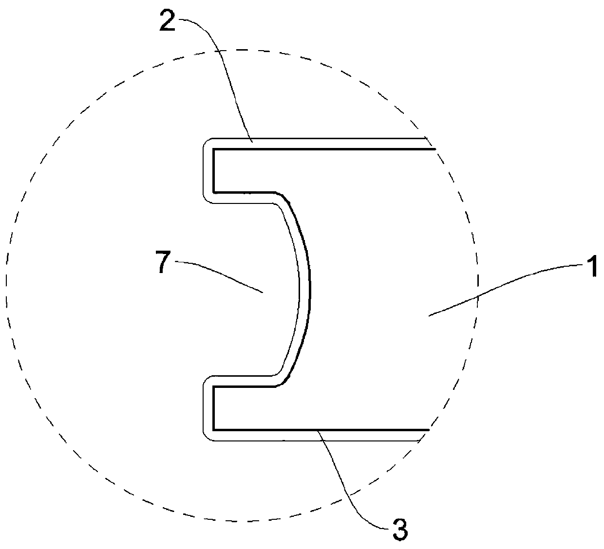
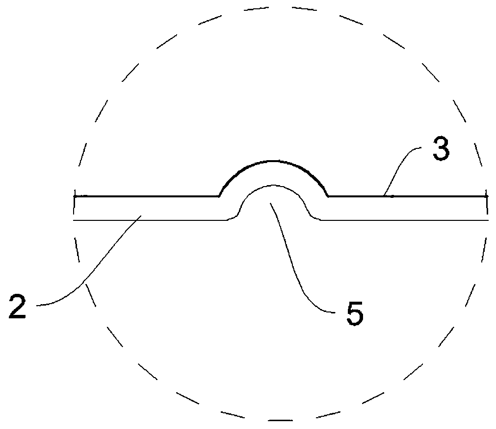
[0036] A kind of container wood-plastic floor, such as Figure 1-2 As shown, it includes a core layer 1 and a skin layer 2 wrapping the core layer 1, a reinforcement layer 3 is provided between the core layer 1 and the skin layer 2, the thickness of the skin layer 2 is 0.6-2 mm, and the thickness of the core layer 1 is 15-2 mm. 25mm; the core layer 1 and the cortex 2 are wood-plastic boards, and the core layer 1 is mixed with short fibers; the reinforcement layer 3 is a mesh structure with an aperture of 1-5mm, and the material is glass fiber or metal; The middle part of the core layer 1 is provided with through holes 4 at intervals; the lower surface of the cortex 2 is provided with a number of positioning holes 5 (such as image 3 As shown), tenons 6 and tenon grooves 7 are respectively provided at the same horizontal position on both sides of the cortex 2; the core layer 1, cortex 2 and reinforcement layer 3 are integrally formed by co-extrusion process.
[0037]The raw ma...
Embodiment 2
[0040] A kind of production equipment of container wood-plastic floor, such as Figure 4-5 Shown, comprise the first extruder 8, the second extruder 9, upper fiber network frame 10, lower fiber network frame 11, mold 12 and shaping table 13; Described first extruder 8 is used for extruding core layer, the second extruder 9 is used to extrude the cortex, and the extrusion ports of the first extruder 8 and the second extruder 9 are docked with the mold 12; the upper fiber grid 10 and the lower fiber grid 11 It is arranged on the upper and lower sides of the mold 12 ; the mold 12 includes a die head 121 , and the shaping table 13 is arranged at the outlet end of the die head 121 .
[0041] Utilize above-mentioned production equipment to prepare the method for container wood-plastic floor described in embodiment 1, comprise the following steps:
[0042] S1. Release the net: pull the glass fiber net into the mold 12 in advance, the two ends of the net stretch out from the mold 12,...
Embodiment 3
[0047] This embodiment provides an optimized reinforcement layer 3, such as Figure 6 As shown, it is a glass fiber mesh, the surface of the glass fiber mesh is provided with several support parts 31 at intervals, and the support parts 31 can be arranged on the surface of the network structure combined with the core layer, and the support parts 31 are elongated The protrusion is integrally formed with the glass fiber net, and the setting direction of the support part 31 in this embodiment is perpendicular to the running direction of the glass fiber net in the mold. When the core layer 1 drives the glass fiber net to advance together, the support part 31 is embedded in the molten state. In the core layer 1, not only the combination level of the glass fiber mesh and the core layer is improved, but more importantly, it plays a role of fixing and limiting, so that the mesh part of the glass fiber mesh is not easy to deform or bend, and the entire glass fiber mesh is flat Attached ...
PUM
| Property | Measurement | Unit |
|---|---|---|
| length | aaaaa | aaaaa |
| modulus | aaaaa | aaaaa |
| pore size | aaaaa | aaaaa |
Abstract
Description
Claims
Application Information
 - R&D
- Intellectual Property
- Life Sciences
- Materials
- Tech Scout
- Unparalleled Data Quality
- Higher Quality Content
- 60% Fewer Hallucinations
Browse by: Latest US Patents, China's latest patents, Technical Efficacy Thesaurus, Application Domain, Technology Topic, Popular Technical Reports.
© 2025 PatSnap. All rights reserved.Legal|Privacy policy|Modern Slavery Act Transparency Statement|Sitemap|About US| Contact US: help@patsnap.com


