A gripper mechanism based on logistics transportation and loading and unloading

A clamping and logistics technology, applied in transportation and packaging, destacking of objects, stacking of objects, etc., can solve the problem of high energy consumption, poor stability and controllability, low energy consumption and stability of the gripper mechanism. problems such as controllability and maintenance costs, to achieve the effects of simple power structure composition and control system, high stability and reliability, and low energy consumption and configuration costs

Active Publication Date: 2021-11-30
云南迦南飞奇科技有限公司
View PDF5 Cites 1 Cited by
  • Summary
  • Abstract
  • Description
  • Claims
  • Application Information

AI Technical Summary

Problems solved by technology

[0006] The invention provides a gripper mechanism based on logistics transportation and loading and unloading, which has optimized power structure and control system, low energy consumption, high stability and controllability, low configuration cost and future maintenance cost Advantages, it solves the complex power structure composition and control system of the gripper mechanism in the existing palletizing equipment, and at least two sets of power output devices are required, one set provides power for driving the goods to move up, down, left, and right, and the other set for Stable clamping of goods to provide power, resulting in high energy consumption of the clamping gripper mechanism, and a serious loss of power resources. Large goods need to constantly adjust the size of the clamping force to avoid the phenomenon that the goods are squeezed and damaged due to excessive clamping force. The stability and controllability are poor, and for clamping with complex power structure and control system Supporting institutions, the overall configuration cost and the high maintenance cost in the future

Method used


Image

  • A gripper mechanism based on logistics transportation and loading and unloading
  • A gripper mechanism based on logistics transportation and loading and unloading
  • A gripper mechanism based on logistics transportation and loading and unloading

Examples


Embodiment Construction

[0025] The following will clearly and completely describe the technical solutions in the embodiments of the present invention with reference to the accompanying drawings in the embodiments of the present invention. Obviously, the described embodiments are only some, not all, embodiments of the present invention. Based on the embodiments of the present invention, all other embodiments obtained by persons of ordinary skill in the art without making creative efforts belong to the protection scope of the present invention.

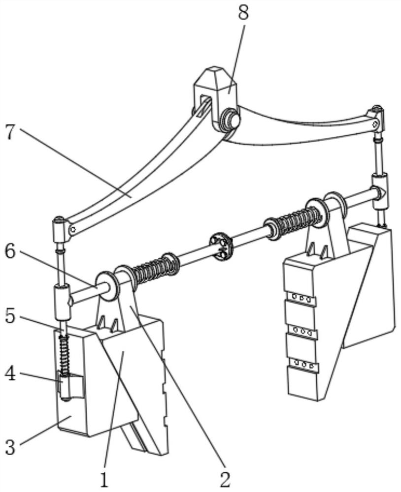
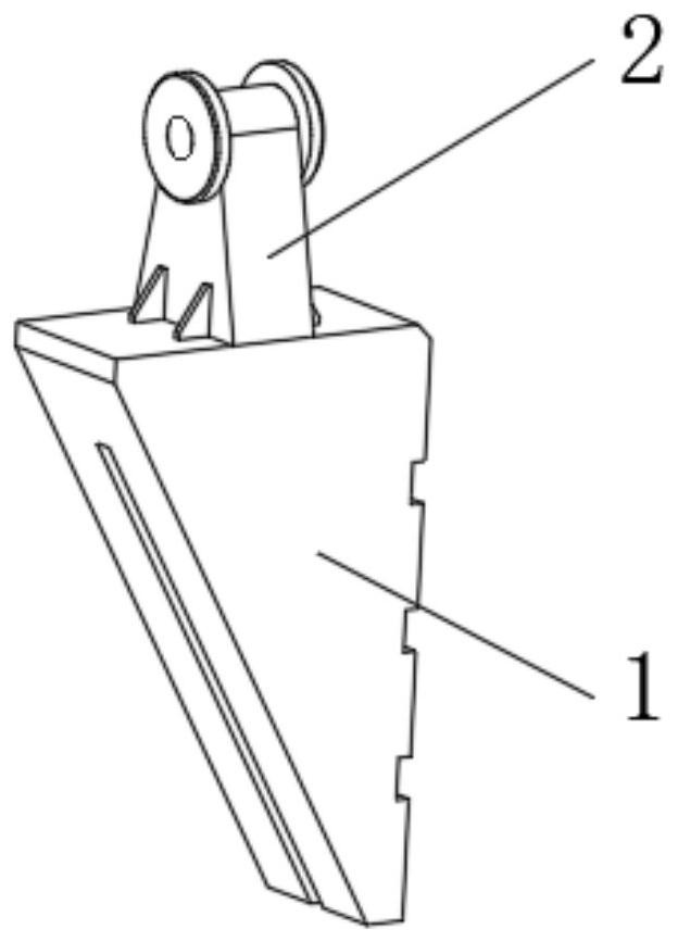
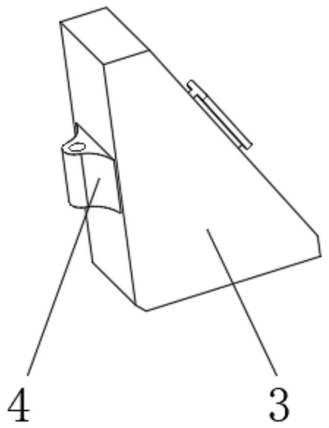
[0026] see figure 1 , a clamping handle mechanism based on logistics transportation loading and unloading, including movable clamping block 1, the number of movable clamping block 1 is set to two groups, the top of movable clamping block 1 is provided with connecting support 2, the side of movable clamping block 1 A push clamp 3 is movably connected, and the middle part of the side of the push clamp 3 is fixedly installed with a fixed support 4, and the inner ...


PUM


Abstract

The invention relates to the technical field of automatic palletizing equipment, and discloses a gripper mechanism based on logistics transportation and loading and unloading. A connecting support is provided, the side of the movable clamping block is movably connected with a pushing clamping block, and the middle part of the side of the pushing clamping block is fixedly installed with a fixed bearing. The clamping handle mechanism based on logistics transportation and loading and unloading, through the setting of the movable clamping block and the pushing clamping block, when the pushing clamping block is subjected to tension and moves vertically upwards, under the action of its inclined surface, the movable clamping block can move toward the Automatic inner movement and automatic clamping of goods, compared with the existing clamping mechanism, there is no need to configure other power output devices to clamp goods, the entire power structure composition and control system are relatively simple, greatly optimized The structural composition of the entire clamping handle has low energy consumption and configuration costs, and a wide range of applications.

Description

technical field [0001] The invention relates to the technical field of automatic palletizing equipment, in particular to a gripper mechanism based on logistics transportation loading and unloading. Background technique [0002] With the continuous development and growth of my country's logistics and transportation industry, it is often necessary to load and unload goods from various places in various distribution warehouses. Medium and large throughput, and the efficiency of manual loading, unloading and handling is relatively low, and the cost of transshipment is high. Therefore, in order to meet the huge throughput of the distribution warehouse, palletizing equipment is usually used to carry up and down the goods. [0003] However, the power structure and control system of the gripper mechanism in the existing palletizing equipment are complicated, and at least two sets of power output devices are required, one set provides power to drive the goods to move up, down, left, a...

Claims


Application Information

Patent Timeline
Patent Type & Authority Patents(China)
IPC IPC(8): B65G61/00B65G47/90B65G1/04
CPCB65G1/04B65G47/901B65G61/00
Inventor 张海林
Owner 云南迦南飞奇科技有限公司
Why Eureka
Try Eureka