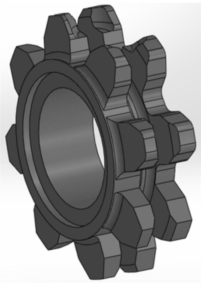
A method for automatic surfacing welding on the surface of mine sprocket socket
An automatic surfacing and chain nest technology, applied in the field of additive manufacturing, can solve the problems of non-automation and low welding efficiency, and achieve the effect of improving efficiency, efficient automatic production, and realizing efficient automatic production.
- Summary
- Abstract
- Description
- Claims
- Application Information
AI Technical Summary
Problems solved by technology
Method used
Image
Examples
specific Embodiment approach 1
[0033] DETAILED DESCRIPTION One: Combination Figure 1 to 16 In the present embodiment, the automatic surfaculating method of a mineral sprocket chain socket includes the following steps:
[0034] Step 1: Plan the welding torch walking path:
[0035] First, surface information is obtained; then the surface of the nest is multi-layer multi-channel stack; for a certain layer of surfacing, the solder torch is planned to fill the walking route on the solder torch; obtain the discrete point; for discrete points, Get the radiode information of the final surface of the final surface; determining the robot's push post during the surfacing process; transforming the path points and attitude information into the robot executing program file;
[0036] Step 2: Using the line structure light sensor to determine the user coordinate system:
[0037] Through the relationship between the pixel coordinate system S and the camera coordinate C, the integrated camera coordinate system C relative tool co...
specific Embodiment approach 2
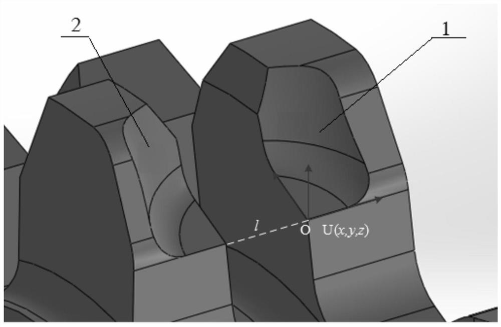
[0039] DETAILED DESCRIPTION 2: Combination Figure 1 to 16 In this embodiment, the process of obtaining surface information in the steps of the present embodiment includes: first analyzing the morphological characteristics of the sprocket before designing the surfacing path, and the sprocket is made of more pairs of uniform distribution, the chain nest opposite The wheel tooth and the hollow hub are composed of the chain slot, and the shape is composed of a surface and a plane, which is a three-dimensional information characterized for each link surface, and the feature point O and the user coordinate system U (X, Y, Z), o Select the chain nest. The two boundary lines of the planar portion, extending along the two boundaries to the X-axis and the Y-axis, determine the Z axis according to the right hand law, to obtain the user coordinate system U (X, Y, Z), thereby obtaining two symmetric settings Surface information of the sleeve surface 1 and the link surface 2 2 relative to U (X,...
specific Embodiment approach 3
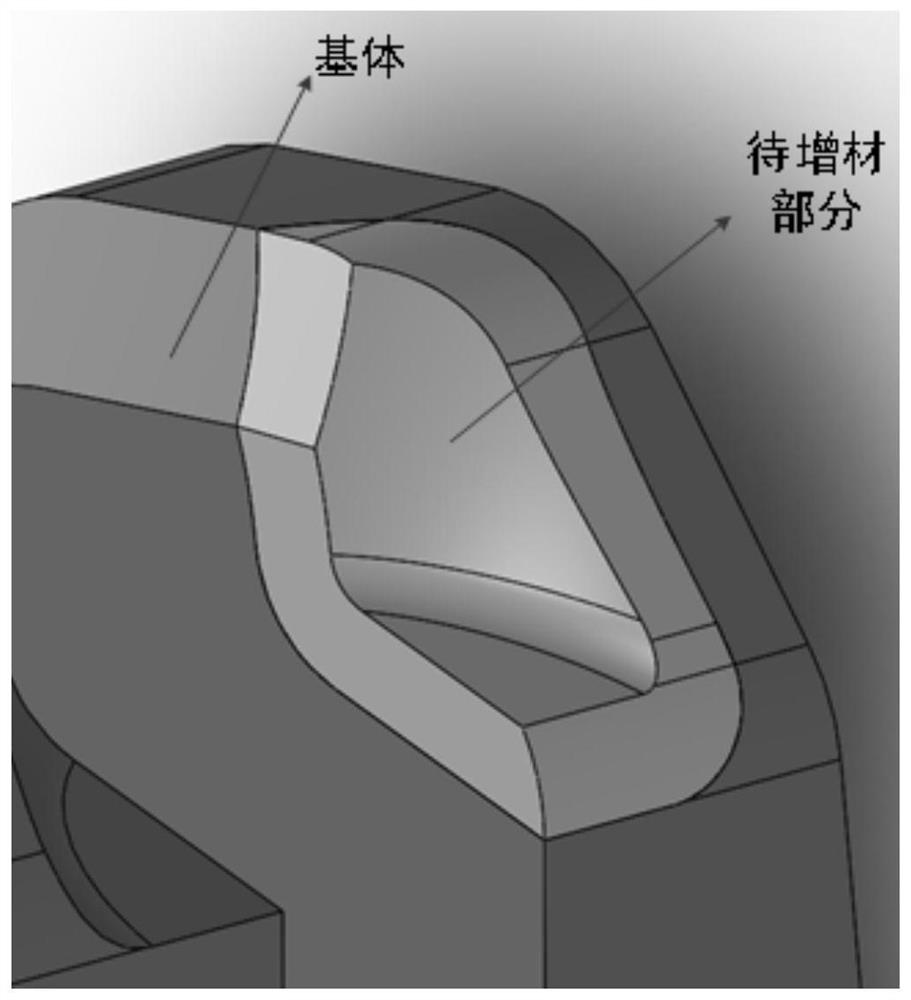
[0040] Specific Embodiment 3: Combination Figure 1 to 16 In the present embodiment, the process of multi-layer multi-tunnel surface is performed in the steps of the step of the step of the present embodiment, including: using software first, the surface of the unfilled linked socket is equivalent, and the slope surface The specific distance is shifted in the direction of each point of the phase vector direction, and then the new offset discrete point is screened, fitted to the surface of the initial strand surface specific offset distance. Use the contour surface of the required surfacing Curved layer Cut, remove the part of the edge, get the surface that eventually needs to be solder The technical features that are not disclosed in the present embodiment are the same as those of the specific embodiment.
[0041] In this embodiment, the SolidWorks software first is first equivalent to the surface surface of the unsolded linked socket.
PUM
| Property | Measurement | Unit |
|---|---|---|
| thickness | aaaaa | aaaaa |
Abstract
Description
Claims
Application Information
 - R&D
- Intellectual Property
- Life Sciences
- Materials
- Tech Scout
- Unparalleled Data Quality
- Higher Quality Content
- 60% Fewer Hallucinations
Browse by: Latest US Patents, China's latest patents, Technical Efficacy Thesaurus, Application Domain, Technology Topic, Popular Technical Reports.
© 2025 PatSnap. All rights reserved.Legal|Privacy policy|Modern Slavery Act Transparency Statement|Sitemap|About US| Contact US: help@patsnap.com


