Knife handle automatic clamping mechanism

A technology of clamping mechanism and tool handle, which is applied in the direction of clamping, metal processing machinery parts, support, etc., can solve the problems of low automation efficiency and unfavorable promotion of CNC machining centers, etc., and achieve precise automatic positioning and reliable clamping of tool handles Effect

Pending Publication Date: 2020-08-21
辽宁航空智能制造研究院有限公司
View PDF4 Cites 1 Cited by
  • Summary
  • Abstract
  • Description
  • Claims
  • Application Information

AI Technical Summary

Problems solved by technology

[0003] In the CNC machining center at the present stage, the upper and lower tool replacement of the tool is carried out manually or by the clamping mechanism of the tool handle clamping the card slot of the tool handle. Since the tool handle is fixed on the tool holder through the card slot on the tool handle, the tool In the process of up and down the knife, it is necessary to use manual assistance to position the tool in the machining center and up and down the knife, the automation efficiency is low, which is not conducive to the promotion of CNC machining centers

Method used


Image

  • Knife handle automatic clamping mechanism
  • Knife handle automatic clamping mechanism
  • Knife handle automatic clamping mechanism

Examples


Embodiment Construction

[0033] In order to make the purpose, technical solution and advantages of the technical solution clearer, the technical solution will be further described in detail below in conjunction with specific embodiments. It should be understood that these descriptions are only exemplary, and are not intended to limit the scope of the technical solution.

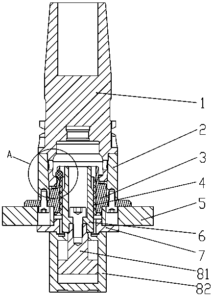
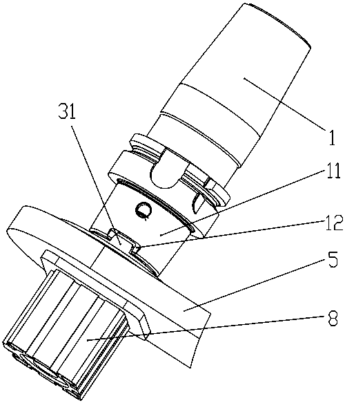
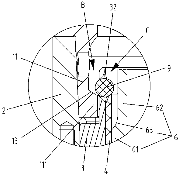
[0034] Such as Figure 1-Figure 3 As shown, the knife handle automatic clamping mechanism proposed in this embodiment includes a knife handle 1, a knife seat 2, a knife seat inner bushing 3, a lifting column 6, a cylinder 8 and a locking steel ball 9, wherein the tail end of the knife handle 1 It is cylindrical, and the tail end of the handle 1 extends toward the axial direction of the handle 1 to form a ring-shaped inner edge structure 111. The end surface of the inner edge structure 111 facing the head side of the handle 1 is an inner slope 13 of the handle. The tail end of the knife handle 1 has a knife handle limit groove 12 ext...


PUM


Abstract

The invention relates to the technical field of cutting tool clamps, in particular to a knife handle automatic clamping mechanism. A knife handle limiting groove is formed in the tail end of a knife handle; the outer ring surface of a knife holder inner lining is in an annular stepped shape; the tail end of the knife holder inner lining is installed at the tail part of a knife holder in an inserted mode; a steel ball maintaining groove is formed in the head segment of the knife holder inner lining; a knife handle aligning block is arranged on the outer ring surface of the head segment of the knife holder inner lining; the outer ring surface of a lifting column is in an annular stepped shape and the outer diameter of the head part column segment is smaller than the outer diameter of the tail part column segment; the lifting column is installed in the knife holder inner lining in an inserted mode; an air cylinder is in rigid connection with the lifting column and can drive the lifting column to slide; a fastening steel ball is arranged in the steel ball maintaining groove; a knife handle is inserted in a gap between the knife holder and the head segment of the knife holder inner lining; the tail part end face of the knife handle abuts against an annular stepped face of the knife holder inner lining; and the knife handle aligning block is embedded into the knife handle limiting groove. The knife handle automatic clamping mechanism realizes automatic positioning and reliable clamping of the knife handle without influencing service life and performance of the knife handle.

Description

technical field [0001] The invention relates to the technical field of tool holders, in particular to an automatic tool holder clamping mechanism. Background technique [0002] With the continuous development of modern industrial production technology, the coverage area of ​​CNC machining in the actual production site is getting larger and larger, and its position is becoming more and more important. It is the core component of modern manufacturing technology. As an extremely important production resource in CNC workshops, cutting tools have a wide variety and a huge quantity. Relevant statistics show that the cost of the tool itself only accounts for 3% to 5% of the production cost, while the indirect costs related to auxiliary links such as tool management, preparation and distribution are far greater than this proportion. [0003] In the CNC machining center at the present stage, the upper and lower tool replacement of the tool is carried out manually or by the clamping ...

Claims


Application Information

Patent Timeline
Patent Type & Authority Applications(China)
IPC IPC(8): B23Q7/04B23Q3/155
CPCB23Q3/1552B23Q7/046
Inventor 李涛白钰刘启伟
Owner 辽宁航空智能制造研究院有限公司
Why Eureka
Try Eureka