Parallel plate optical parameter measuring method based on sampling function

A parallel plate, sampling function technology, applied in optical instrument testing, measuring devices, testing optical performance and other directions, can solve the problems of decreased measurement efficiency, long operation time, low harmonic order, etc., and achieve the elimination of reference surface surface accuracy. effect, avoid extra work, reduce measurement error

Inactive Publication Date: 2020-08-21
NANJING UNIV OF SCI & TECH
View PDF3 Cites 2 Cited by
  • Summary
  • Abstract
  • Description
  • Claims
  • Application Information

AI Technical Summary

Problems solved by technology

However, the algorithm is sensitive to precise frequency detuning or shifting due to refractive index dispersion and wavelength tuning nonlinearities
When there is a certain nonlinear error in wavelength tuning and phase shifting, directly using the fast Fourier transform algorithm will affect the measurement accuracy, and additional optical methods are required to calibrate the relationship between the wavelength change and the voltage, and the process is too complicated and cumbersome , making the measurement efficiency drop
Yangjin Kim proposed a 17-sample algorithm in "Measurement of optical thickness variation of BK7 plate by wavelength tuning interferometry" (Optics Express, 2015, 23(17): 22928-22938), but the harmonic order suppressed by the algorithm Low, not suitable for measurement of optical uniformity
We previously proposed a measurement method based on non-uniform Fourier transform in "Optical homogeneity measurement of parallel plates by wavelength-tuning interferometry using nonuniform fast Fourier transform" (Optics Express, 2019, 27(9): 13072-13082) , using non-uniform Fourier transform spectrum analysis to reduce the nonlinear error of wavelength phase shifting, but this method requires a large number of interferograms, takes a long time to operate, and is easily affected by environmental disturbances

Method used


Image

  • Parallel plate optical parameter measuring method based on sampling function
  • Parallel plate optical parameter measuring method based on sampling function
  • Parallel plate optical parameter measuring method based on sampling function

Examples


Embodiment Construction

[0018] The present invention will be further described below in conjunction with the accompanying drawings and specific embodiments.

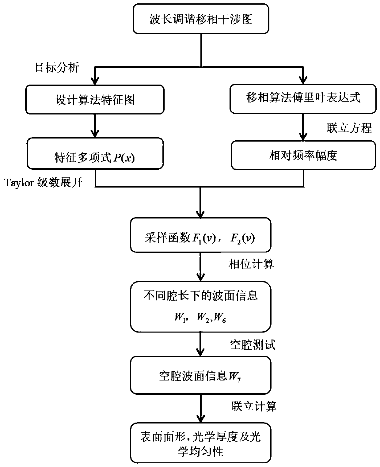
[0019] combine figure 1 , a kind of measuring method of the parallel plate optical parameter based on sampling function of the present invention, comprises the following steps:

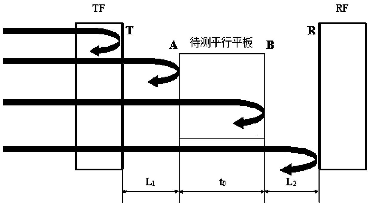
[0020] Step 1. In the interference cavity of the Fizeau wavelength phase-shifting interferometer, place the parallel plate to be measured between the transmission reference plane T and the reflection reference plane R of the interference cavity, and place the Fizeau interferometer between the reference surface and the surface to be measured The distance and the optical thickness of the plate to be tested are adjusted to an integer ratio to ensure that the frequencies of all interfering signals are roughly centered on the harmonic frequency. After setting the number N of interferograms collected and the phase-shift step size, phase-shift sampling is performed to obtain...


PUM


Abstract

The invention discloses a parallel plate optical parameter measuring method based on a sampling function, and the method comprises the steps: firstly carrying out phase-shifting sampling in a Fizeau wavelength phase-shifting interferometer, and respectively obtaining interference patterns for placing a to-be-tested parallel plate and a cavity; secondly, obtaining a feature map of a phase shift algorithm according to actual target requirements, writing a feature polynomial of the phase shift algorithm, expanding by utilizing a Taylor formula to obtain the sampling function of the algorithm, andsubstituting the acquired interference light intensity data into the algorithm for calculation; and finally, extracting phase information at different target frequencies by using different sampling functions, recovering the phase information into wave surface information, and calculating to obtain the surface shape, the optical thickness and the optical uniformity parameter of the to-be-tested parallel flat plate. By designing the sampling function of the phase shift algorithm, measurement errors caused by frequency shift due to refractive index dispersion and wavelength tuning nonlinearity are reduced, required interference patterns are few, operation is simple, and the method can be used for high-precision measurement of optical parameters of large-aperture optical materials.

Description

technical field [0001] The invention relates to the field of optical interferometric measurement, in particular to a method for measuring optical parameters of a parallel flat plate based on a sampling function. Background technique [0002] Optical transmission materials are an important part of optical materials, and their optical properties play an important role in the entire optical system. The optical parameters of optically transparent materials mainly include optical uniformity, optical thickness, and surface shape. If the optical parameters are not consistent, the wavefront of the light wave will be changed when the light wave is transmitted through, thus degrading the performance of the optical system. When the optical parameters change greatly and exceed a certain range, it will cause serious deformation of the transmitted wave surface, making it impossible to recover through optical cold processing and assembly. Therefore, it is necessary to achieve high-precis...

Claims


Application Information

Patent Timeline
IPC IPC(8): G01M11/02
CPCG01M11/0271
Inventor 郭仁慧宋萍萍刘成兴许雅付航李建欣朱日宏陈磊何勇
Owner NANJING UNIV OF SCI & TECH
Why Eureka
Try Eureka