
Machining device for building decoration parts

A technology for architectural decoration and processing equipment, which is applied in the field of architectural decorative parts production equipment, can solve the problems of low automation, low production efficiency, and high labor intensity of staff, and achieve the goals of reducing labor intensity, increasing automation, and improving work efficiency Effect

Inactive Publication Date: 2020-08-25
JIANGSU ZHONGXUAN CONSTR
View PDF28 Cites 0 Cited by
  • Summary
  • Abstract
  • Description
  • Claims
  • Application Information

AI Technical Summary

Problems solved by technology

[0005] In order to overcome the above-mentioned defects of the prior art, an embodiment of the present invention provides a processing device for building decoration parts. The technical problem to be solved by the invention is: the existing processing equipment for building decoration parts has a low degree of automation, and the labor intensity of the staff is low. Large and low production efficiency, it is difficult to adapt to mass production

Method used


Image

  • Machining device for building decoration parts
  • Machining device for building decoration parts
  • Machining device for building decoration parts

Examples


Embodiment Construction

[0034] Example embodiments will now be described more fully with reference to the accompanying drawings. Example embodiments may, however, be embodied in many forms and should not be construed as limited to the examples set forth herein; Fully conveyed to those skilled in the art. The drawings are merely schematic illustrations of the present disclosure and are not necessarily drawn to scale. The same reference numerals in the drawings denote the same or similar parts, and thus repeated descriptions thereof will be omitted.

[0035] Furthermore, the described features, structures, or characteristics may be combined in any suitable manner in one or more example embodiments. In the following description, numerous specific details are provided in order to give a thorough understanding of example embodiments of the present disclosure. However, those skilled in the art will appreciate that the technical solutions of the present disclosure may be practiced without one or more of ...


PUM


Abstract

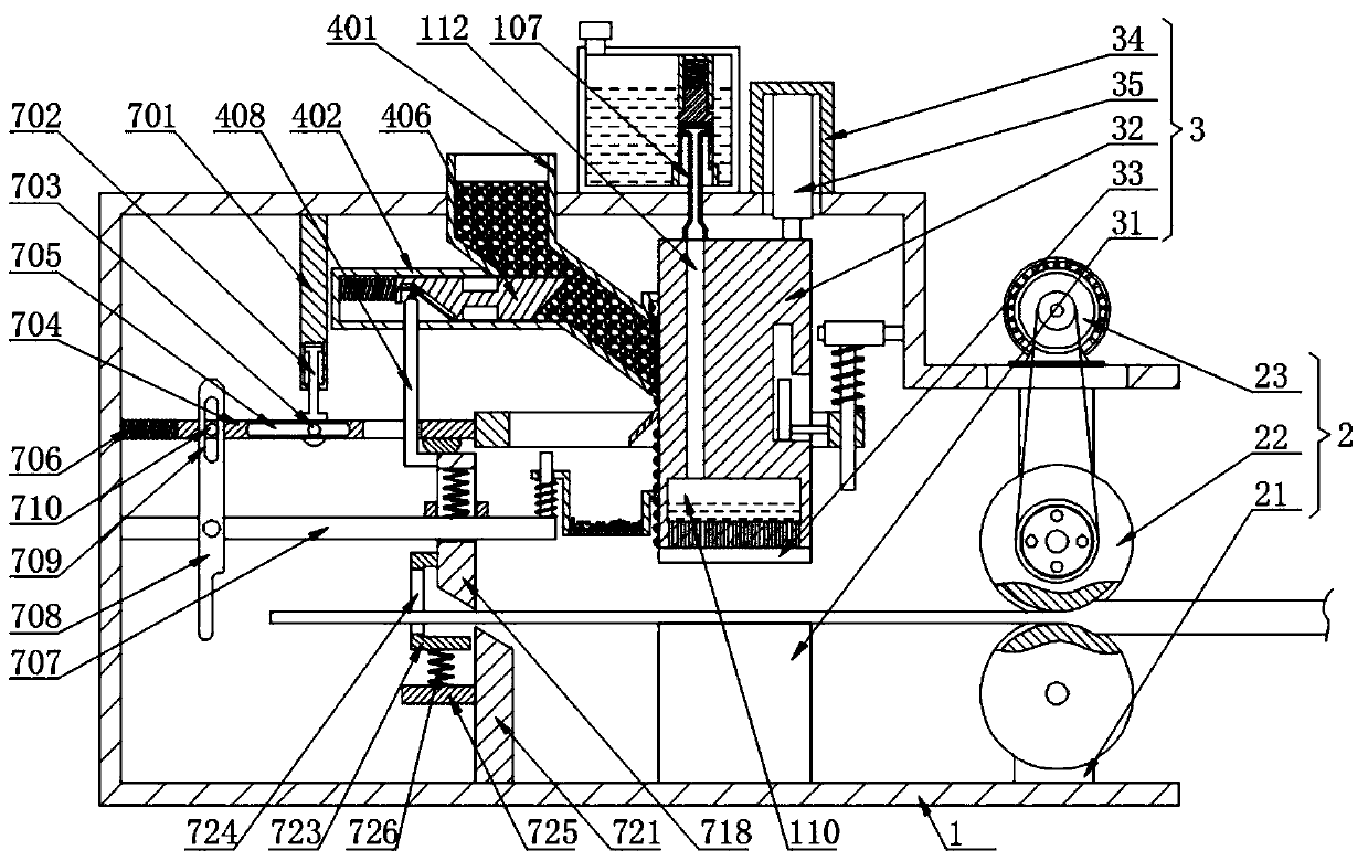
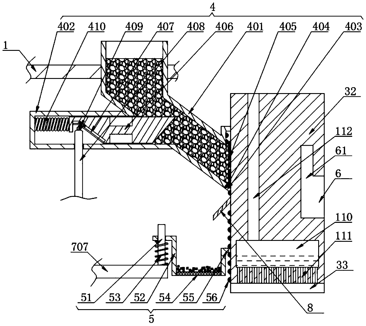
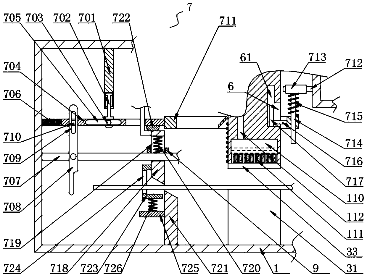
The invention discloses a machining device for building decoration parts, and particularly relates to the technical field of building decoration part production equipment. The machining device comprises a rack, wherein an extrusion conveying mechanism is arranged on one side of the interior of the rack, a forming mechanism is arranged on one side of the extrusion conveying mechanism, and a grinding mechanism far away from one side of the extrusion conveying mechanism is arranged on one side of the forming mechanism. According to the device, through the arrangement of the extrusion conveying mechanism, the forming mechanism, the grinding mechanism, a vibrating mechanism, a cutting mechanism and a glue feeding mechanism, conveying and forming of decorative part bars are achieved, meanwhile,the functions of gluing the decorative part bars and enabling glue to be distributed evenly are achieved in the forming process, in the up-down moving process of a forming column, the effects of grinding and screening a fluorite are further achieved, fluorescent powder can be automatically sprayed to the decorating part bars, finally, a trigger rod is pushed through the decorating part bars, and the function that the forming column drives an upper cut-off tool to cut off the decorating part bars is further achieved.

Description

technical field [0001] The invention relates to the technical field of production equipment for building decorations, and more specifically, the invention relates to a processing device for building decorations. Background technique [0002] In recent years, my country's real estate and architectural decoration industries have developed rapidly, and the building decoration materials industry has also followed suit. Architectural decoration refers to architectural decoration projects. In this process, the decoration must be organically combined with the decorated object to become a unified and harmonious whole in order to enrich the artistic image, expand the artistic expression, strengthen the aesthetic effect, and improve its function, economic value and social benefits. Architectural decoration can relieve people's anxiety. [0003] However, the existing processing equipment for architectural decorative parts has a relatively simple structure and a low degree of automation....

Claims


Application Information

Patent Timeline
Patent Type & Authority Applications(China)
IPC IPC(8): B21C23/00B21C33/00B21C35/04B21C37/00
CPCB21C23/00B21C33/006B21C35/04B21C37/00
Inventor 程新华
Owner JIANGSU ZHONGXUAN CONSTR
Learn More