Eureka AIR delivers breakthrough ideas for toughest innovation challenges, trusted by R&D personnel around the world.

Forging technology of single-oil-groove bevel gear

A technology of helical gears and oil grooves is applied in the field of forging technology of helical gears with single oil grooves, which can solve the problems affecting the machining accuracy of gears and the overall deformation of the gears, and achieve the effects of improving machining efficiency, ensuring smoothness and increasing machining accuracy.

Active Publication Date: 2020-08-25
西伯瀚(泰兴)传动技术有限公司
View PDF6 Cites 1 Cited by
  • Summary
  • Abstract
  • Description
  • Claims
  • Application Information

AI Technical Summary

Problems solved by technology

[0005] In order to make up for the deficiencies of the existing technology, solve the problem that in the existing gear hobbing technology, the heated gear blank is quickly taken out of the heating furnace, and then the gear blank is installed on the rotary table, and then the gear blank is rotated and squeezed by the rolling wheel The outer edge, so that the outer edge of the gear blank is gradually extruded to form a tooth shape, and the center hole of the gear is subjected to radial pressure, so that the gear with a higher temperature will be deformed when it is strongly squeezed by the rolling wheel, which affects the machining accuracy of the gear. A kind of forging process of single oil groove helical gear proposed by the present invention

Method used

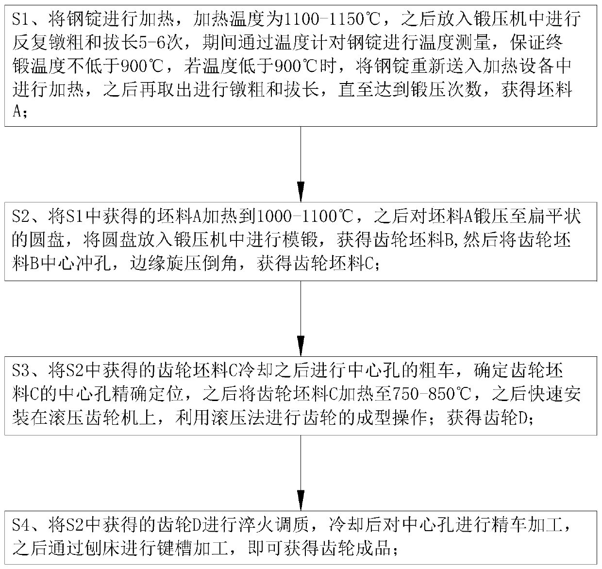
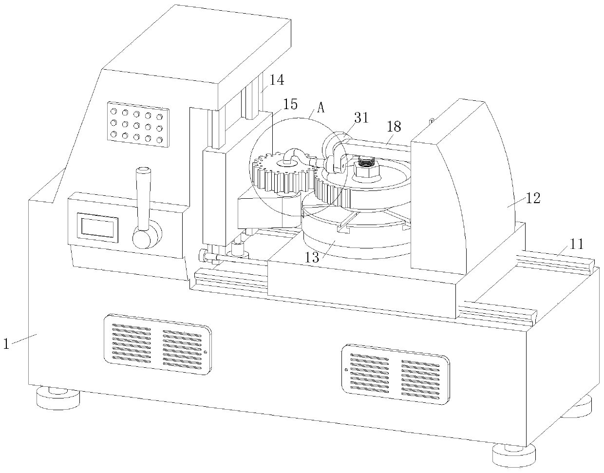
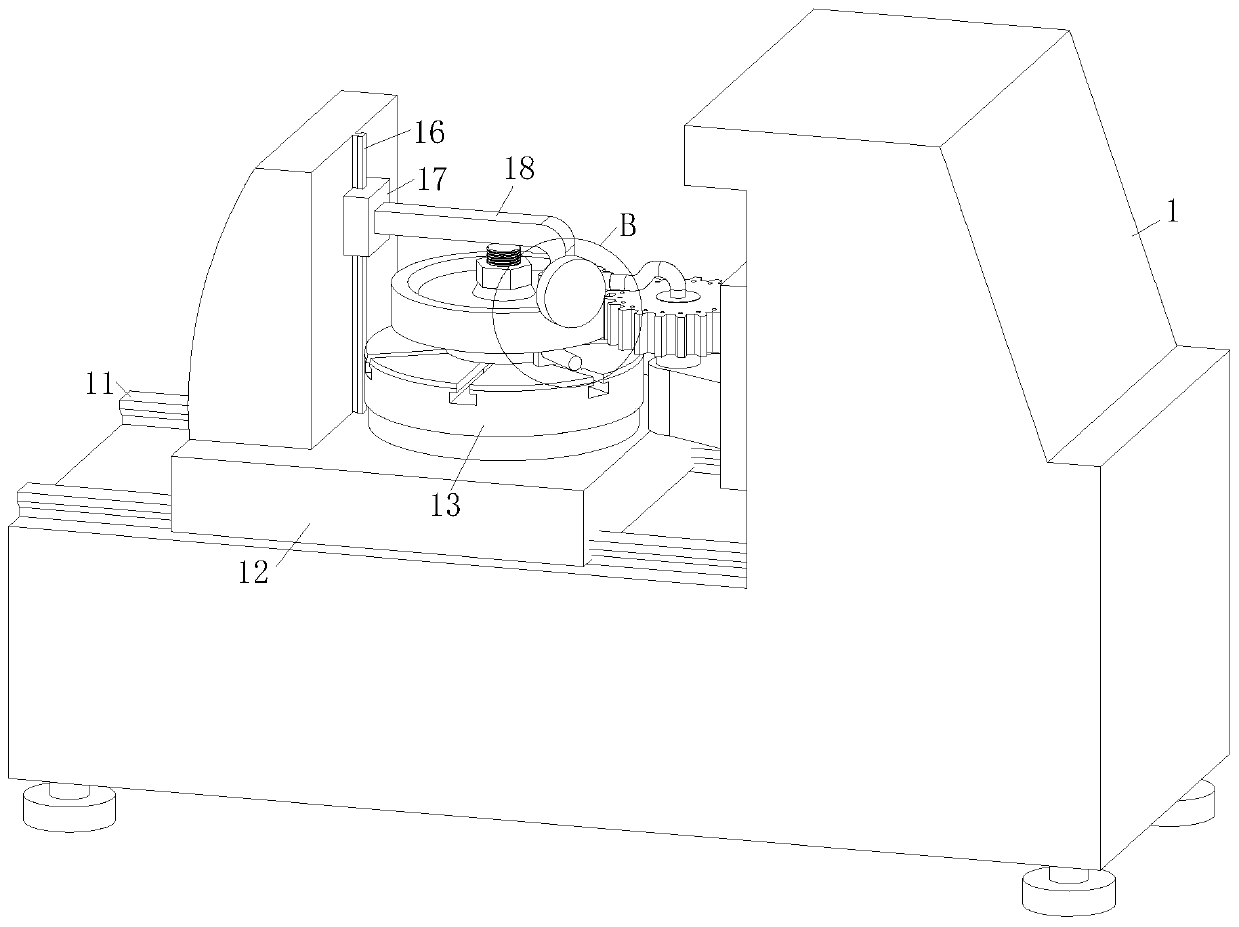

Image

  • Forging technology of single-oil-groove bevel gear
  • Forging technology of single-oil-groove bevel gear
  • Forging technology of single-oil-groove bevel gear

Examples


Embodiment approach

[0036] As an embodiment of the present invention, the end of the tapered portion 22 away from the bracket 18 is provided with a cylindrical shaping portion 23, the shaping portion 23 is used to reduce the lug formed in the axial direction when the gear blank is rolled; when the gear When the outer edge of the blank is squeezed by the rolling wheel 2, the rolling wheel 2 squeezes the gear blank so that the outer edge of the high-temperature gear blank deforms and flows to form a tooth shape. At this time, a part of the gear blank is deformed to the axial direction of the center hole of the gear blank to form The lug increases the follow-up cutting work of the gear. The end of the tapered part 22 away from the bracket 18 is provided with a cylindrical shaping part 23, which squeezes and shapes both sides of the gear, thereby ensuring the smoothness of both sides of the gear and avoiding the occurrence of lugs. , thereby improving the gear machining efficiency.

[0037] As an emb...


PUM


Abstract

The invention belongs to the technical field of gear manufacture and specifically provides a forging technology of a single-oil-groove bevel gear. A gear rolling machine adopted in the forging technology comprises a machine frame; the top of the machine frame is fixedly connected with a horizontal sliding rail, and the horizontal sliding rail is in sliding connection with a worktable; the worktable is rotationally connected with a round rotary disk used for fixing a gear blank; one side of the machine frame is fixedly connected with a first sliding rail, and the first sliding rail is in sliding connection with a drive unit used for driving a rolling wheel to rotate and squeeze the circumference of the gear blank to form a tooth shape; a second sliding rail is arranged on the side, away from the rolling wheel, of the worktable and is in sliding connection with a supporting unit; and the supporting unit is fixedly connected with a support, the end, away from the supporting unit, of the support is rotationally connected with a supporting wheel, and a conic part is arranged at the end, away from the support, of the supporting wheel and matched with the shoulder on the outer edge of thegear. The shoulder on the outer edge of the gear is supported by the conic part, deformation of the gear blank in the tooth rolling process is reduced, and gear machining accuracy is improved.

Description

technical field [0001] The invention belongs to the technical field of gear manufacturing, in particular to a forging process of a single oil groove helical gear. Background technique [0002] A gear is a mechanical element with gears on the rim that continuously mesh to transmit motion and power. The application of gears in transmission has appeared very early. At the end of the 19th century, the principle of generative gear cutting method and special machine tools and cutting tools using this principle appeared one after another. With the development of production, the stability of gear operation was paid more attention. The gear is a common part often used in mechanical transmission. The gear is made of high-quality high-strength alloy steel, and the surface is carburized and hardened. It has a strong bearing capacity and is durable. In practical applications, helical gears are widely used in high-speed and heavy-duty occasions due to their stable transmission, low impa...

Claims


Application Information

Patent Timeline
Patent Type & Authority Applications(China)
IPC IPC(8): B23P23/06B23Q11/10
CPCB23P23/06B23Q11/10
Inventor 徐云涛程顺平
Owner 西伯瀚(泰兴)传动技术有限公司
Why Eureka
Eureka Blog
Learn More