Polishing device for machining stainless steel product

A polishing device, stainless steel technology, applied in the direction of manufacturing tools, grinding drive devices, metal processing equipment, etc., can solve the problems of weakening the electrolytic chemical polishing effect, small electrolyte flow area, slow electrolysis speed, etc., to improve the polishing effect, Accelerates the electrolysis effect and prevents leakage

Inactive Publication Date: 2020-08-25
SUZHOU SAISHUOLA STAINLESS STEEL PROD CO LTD
View PDF1 Cites 7 Cited by
  • Summary
  • Abstract
  • Description
  • Claims
  • Application Information

AI Technical Summary

Problems solved by technology

However, this device also has certain defects. For example, only through electrolytic chemical polishing, some sticky dust substances attached to the surface of stainless steel products are not easy to remove, which weakens the effect of electrolytic chemical polishing; way, since the gas supply is always in one direction, the flow area of ​​the electrolyte is smaller and the electrolysis speed is slower

Method used


Image

  • Polishing device for machining stainless steel product
  • Polishing device for machining stainless steel product
  • Polishing device for machining stainless steel product

Examples


Embodiment 1

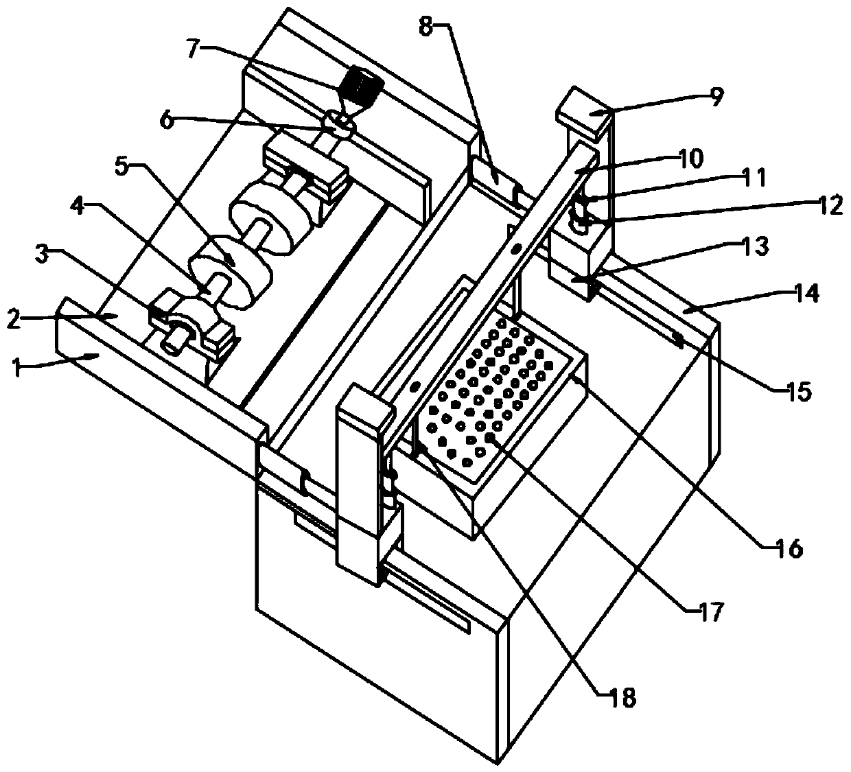
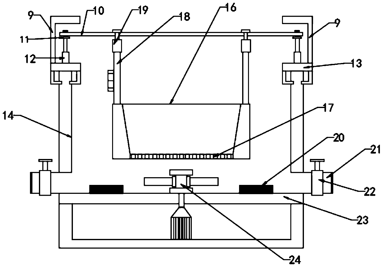
[0018] see figure 1 with figure 2 , in Embodiment 1 of the present invention, a polishing device for processing stainless steel products, which includes: a polishing table 2 and an electrolytic box 14, the electrolytic box 14 is arranged on one side of the polishing table 2, and a polishing assembly is installed on the polishing table 2; The inside of the electrolytic box 14 is provided with a soaking box 16, the lower end of the soaking box 16 is provided with a liquid inlet 17, and the left and right sides of the upper end of the soaking box 16 are provided with electrolytic rods 18, which are positive electrolytic rods; the upper end of the electrolytic rod 18 is installed on Inside the installation terminal 19, the installation terminal 19 is arranged at the lower end of the movable plate 10;

[0019] The left and right sides of the movable plate 10 are installed on the supporting plate 11, the second electric telescopic rod 12 is installed on the lower end of the suppor...

Embodiment 2

[0026] Further, the inner wall of the electrolytic box 14 is provided with a limiting groove 15, the slider 13 is in the shape of "Π", and the protrusion at the lower end of the slider 13 is stuck in the limiting groove 15 on the inner wall of the electrolytic box 14. Through this structural design, Slider 13 is not prone to position deviation when sliding and displacing at the upper end of electrolytic box 14 , and when the second electric telescopic rod 12 at the upper end of slider 13 moves, slider 13 is not easy to be disengaged from electrolytic box 14 due to uneven force.

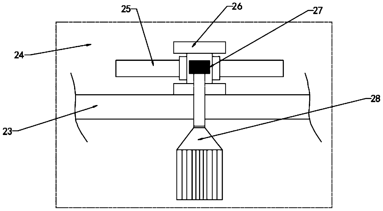
[0027] see image 3 , further, the stirring assembly 24 includes a permanent magnet block 25, a sleeve and a second motor 28, the permanent magnet block 25 and the sleeve are made of non-metallic materials; the permanent magnet block 25 is movably installed on the sleeve, and the sleeve The upper end is provided with a limit block 26; the inside of the sleeve is provided with an electromagnetic block ...


PUM


Abstract

The invention relates to the field of stainless steel product machining equipment, in particular to a polishing device for machining a stainless steel product. The polishing device comprises a grinding table and an electrolytic tank arranged on one side of the grinding table, and a grinding assembly is installed on the grinding table; a soaking tank is arranged in the electrolytic tank, and the right and left sides of the upper end of the soaking tank are provided with electrolytic bars; the upper end of each electrolytic bar is installed in a mounting end arranged at the lower end of a movable plate; the right and left sides of each movable plate are installed on support plates, and the lower ends of the support plates are provided with second electric telescopic rods arranged on a vertical frame; the vertical frame is fixed to a sliding block installed at the upper end of the electrolytic tank slidably; and the bottom end of the electrolytic tank is a separating plate, and a stirringassembly and a negative electrode are installed on the separating plate. According to the polishing device for machining the stainless steel product, through combination of two ways, namely mechanical grinding and polishing and electrochemical polishing; and various stains sticking to the surface of the stainless steel product can be removed, and the polishing effect is improved.

Description

technical field [0001] The invention relates to the field of processing equipment for stainless steel products, in particular to a polishing device for processing stainless steel products. Background technique [0002] Stainless steel products have the characteristics of smooth and firm surface, not easy to accumulate dirt, and easy to clean. Therefore, they are widely used in food processing, catering, brewing, chemical industry, architectural decoration, home decoration, and fine decoration industries, giving people a sense of luxury and nobility. Different effects can be obtained by various treatments on the surface of stainless steel. For example, in order to increase the wear resistance or decoration of stainless steel, it is often necessary to polish, electroplate, and color the stainless steel. Most of the existing stainless steel product polishing technologies are that workers use grinding machines and grinding wheels to polish stainless steel, and the efficiency of ...

Claims


Application Information

Patent Timeline
Patent Type & Authority Applications(China)
IPC IPC(8): B24B29/02B24B27/00B24B47/12C25F3/24C25F7/00B01F13/08
CPCB24B29/02B24B27/0076B24B47/12C25F3/24C25F7/00B01F33/4532
Inventor 史忠平
Owner SUZHOU SAISHUOLA STAINLESS STEEL PROD CO LTD
Why Eureka
Try Eureka