Indirect oil gas condensation recovery device and recovery process thereof

A technology of condensation recovery, oil and gas, applied in the petroleum industry, vapor condensation, liquid hydrocarbon mixture recovery and other directions, can solve the problems of affecting the working performance of the refrigeration system, not considering the recovery of cooling capacity, unstable operation of the refrigeration system, etc., to avoid suction. The effect of the temperature is too low, the electric energy is reduced, and the structure is simple

Active Publication Date: 2020-08-25
中国人民解放军军事科学院国防工程研究院工程防护研究所
View PDF11 Cites 5 Cited by
  • Summary
  • Abstract
  • Description
  • Claims
  • Application Information

AI Technical Summary

Problems solved by technology

The biggest disadvantage of this method is that the oil and gas flow rate and temperature in the oil and gas treatment place vary greatly, which means that the load of oil and gas treatment varies greatly, which will lead to unstable operation of the refrigeration system and greatly affect the performance of the refrigeration system; It is an indirect cooling method that uses heat exchange between the brine and oil and gas, and can respond to changes in the oil and gas load by adjusting the temperature and flow of the brine, so that the system can operate stably
[0004] However, in the existing oil and gas recovery methods using brine, the system structure is often very complicated, and multiple refrigeration systems need to be designed to provide oil and gas treatment temperatures at different stages, and the control of the system is correspondingly much more complicated, and the energy consumption is relatively high , and does not consider the recovery of cooling capacity, the operating cost is relatively high

Method used


Image

  • Indirect oil gas condensation recovery device and recovery process thereof

Examples


Embodiment Construction

[0030] The specific embodiment of the present invention is described in further detail below in conjunction with embodiment accompanying drawing:

[0031] The accompanying drawings are for illustrative purposes only, and should not be construed as limiting the present invention. In order to better illustrate the following embodiments, some components in the drawings will be omitted, enlarged or reduced, and do not represent the size of the actual product; for those skilled in the art, some known structures and their descriptions in the drawings may be omitted. understandable.

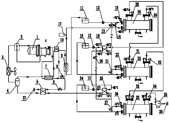
[0032] Such as figure 1 The illustrated embodiment is an indirect oil and gas condensation recovery device and its recovery process. The recovery device includes: an oil and gas delivery system, a cooling system and a low-temperature refrigeration system; the oil and gas delivery system includes a deep cooler 16 and a shallow cooler 23 And precooler 28; Described load cooling system comprises the firs...


PUM


Abstract

The invention discloses an indirect oil gas condensation recovery device and a recovery process thereof. The recovery device comprises an oil gas conveying system, a secondary refrigerant system and alow-temperature refrigerating system. The oil-gas conveying system comprises a precooler, a shallow cooler and a deep cooler. The secondary refrigerant system comprises a first secondary refrigerantcirculation loop, a second secondary refrigerant circulation loop and a third secondary refrigerant circulation loop. The low-temperature refrigerating system comprises a compressor, an oil-gas separator, a condenser gas-liquid separator, a plate heat exchanger, an expansion valve, an evaporator and the like. According to the recovery process of the indirect oil gas condensation recovery device, temperature control of the whole oil gas condensation stage is completed through one refrigerating system, the oil gas condensation process sequentially includes a pre-cooling stage, a shallow coolingstage and a copious cooling stage, a secondary refrigerant in the copious cooling stage and the low-temperature oil gas at the outlet are used to obtain cooling capacity through heat exchange, the oilgas cooling capacity is effectively recycled, the overall energy consumption of the refrigerating system is reduced, and the operation cost of an enterprise is reduced.

Description

technical field [0001] The invention belongs to the technical field of oil and gas recovery, and in particular relates to an indirect oil and gas condensation recovery device and a recovery process thereof. Background technique [0002] Petroleum series products have a lot of loss and waste during storage and transshipment. Oil and gas include a variety of hydrocarbon organic compounds. Improper handling will form chemical smog, which not only endangers safe production but also pollutes the environment. In recent years, the research and engineering on oil and gas recovery and utilization have received extensive attention. To meet the oil and gas discharge standards stipulated by the state, oil and gas recovery and treatment devices must be installed to recover and process the light hydrocarbon components in oil and gas. Currently, the existing oil and gas treatment There are four methods: condensation method, absorption method, adsorption method and membrane separation metho...

Claims


Application Information

Patent Timeline
Patent Type & Authority Applications(China)
IPC IPC(8): C10G5/06B01D5/00
CPCB01D5/0003C10G5/06Y02P70/10
Inventor 陈叶青陈经邱鸿吕林梅郭利平赵强朱新华
Owner 中国人民解放军军事科学院国防工程研究院工程防护研究所
Why Eureka
Try Eureka