
Combination frame structure system with rigid-connection joints

A frame structure and node technology, applied in building components, building structures, floors, etc., can solve the problems of high cost, slow progress, inconvenient construction, etc., to improve the bearing capacity of the column, reduce the size of the column section, save the Effect of construction measure fee

Pending Publication Date: 2020-08-25
宁波优造建筑科技有限公司
View PDF0 Cites 2 Cited by
  • Summary
  • Abstract
  • Description
  • Claims
  • Application Information

AI Technical Summary

Problems solved by technology

[0002] The traditional multi-layer steel frame structure system usually uses steel columns and steel beams as vertical and horizontal force-bearing members, which have problems such as high cost, poor fire resistance and corrosion resistance, and high maintenance costs in the later period, and the requirements for joint connection accuracy are high, and the hoisting speed is slow. If the vertical member adopts the steel pipe concrete composite column, the wall thickness of the steel pipe is relatively large, and the steel consumption is large.
For projects with small storey height, small span and small load, the prefabricated reinforced concrete frame structure system is generally adopted. When columns and floors use different labels, the construction process is complicated and difficult. Therefore, the column section is large, and the beams can only be hoisted layer by layer. The progress is slow and the cost is high. At the same time, the steel bars at the beam-column joints are easy to collide, and the construction is inconvenient.
There is no report on a hybrid frame structure system with rigid connection, which has a large load-bearing capacity of composite columns, multi-layer prefabricated beams can be hoisted at the same time, the beam negative moment reinforcement directly penetrates the nodes in the node area, and the lower part is conveniently welded.

Method used


Image

  • Combination frame structure system with rigid-connection joints
  • Combination frame structure system with rigid-connection joints
  • Combination frame structure system with rigid-connection joints

Examples


Embodiment Construction

[0031] In order to facilitate the understanding of the present invention, the present invention will be described more fully below with reference to the associated drawings. Preferred embodiments of the invention are shown in the accompanying drawings. However, the present invention can be embodied in many different forms and is not limited to the embodiments described herein. On the contrary, the purpose of providing these embodiments is to make the disclosure of the present invention more thorough and comprehensive.

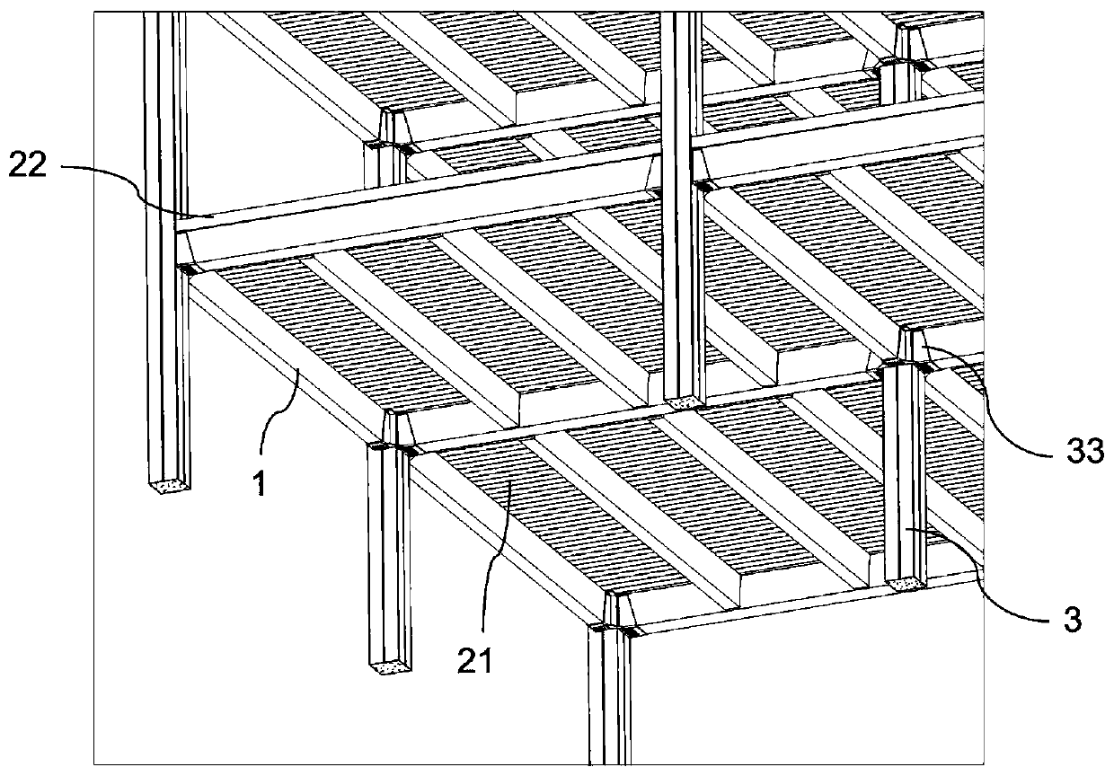
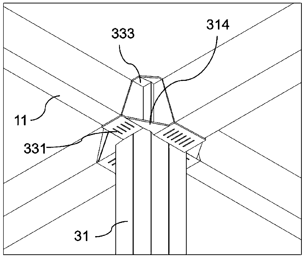
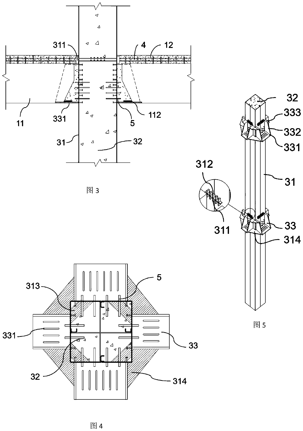
[0032] see Figure 1 to Figure 11 , in the embodiment of a hybrid frame structure system with rigid joint nodes provided by the present invention, it includes prefabricated concrete composite beams 1, steel bearing slab composite floors 2 and thin-walled steel pipe concrete composite columns 3, the prefabricated concrete composite The composite beam 1 includes a prefabricated beam 11 and a cast-in-place part 12, the beam negative moment reinforcement 4 is arr...


PUM


Abstract

The invention discloses a combination frame structure system with rigid-connection joints. The combination frame structure system comprises a prefabricated concrete superposed beam, a steel bearing plate composite floor and a thin-walled concrete-filled steel pipe composite column, the prefabricated concrete superposed beam comprises a prefabricated beam and a cast-in-place part, the cast-in-placepart is internally provided with a beam hogging moment rebar, and the prefabricated beam comprises a main bar and a beam end bottom steel plate; and the steel bearing plate composite floor comprisesa steel bearing plate and reinforced concrete poured on the steel bearing plate, the thin-walled concrete-filled steel pipe composite column comprises a thin-walled steel pipe, steel pipe inner concrete and a joint U-shaped steel corbel, the thin-walled steel pipe is provided with a through hole for reinforcing the steel plate and penetrating the hogging moment rebar at the joint, and a groove-shaped through hole is formed in the bottom of the joint U-shaped steel corbel. The composite column has large bearing capacity, the prefabricated beam can be hoisted at the same time in multiple layers,the beam hogging moment rebar directly penetrates through the joint in the joint area, the lower beam end steel plate is connected by overhead welding after the floor constructed is completed, the construction is convenient, the beam end lower rebar has direct and reliable force transfer, the structure is simple, and the comprehensive cost is low.

Description

technical field [0001] The invention relates to a building structure system, in particular to a hybrid frame structure system with rigid joints. Background technique [0002] The traditional multi-layer steel frame structure system usually uses steel columns and steel beams as vertical and horizontal force-bearing members, which have problems such as high cost, poor fire and corrosion resistance, and high maintenance costs in the later period, and the requirements for joint connection accuracy are high, and the hoisting speed is slow. If the vertical member adopts the steel pipe concrete composite column, the wall thickness of the steel pipe is relatively large, and the steel consumption is large. For projects with small storey height, small span and small load, the prefabricated reinforced concrete frame structure system is generally adopted. When the columns and floor slabs use different labels, the construction process is complicated and difficult. Therefore, the column c...

Claims


Application Information

Patent Timeline
Patent Type & Authority Applications(China)
IPC IPC(8): E04B1/58E04B1/30E04B5/40
CPCE04B1/5831E04B1/30E04B5/40
Inventor 杨峰俞锋波劳红锋
Owner 宁波优造建筑科技有限公司
Learn More