Multifunctional brick paving device

A brick laying device and multi-functional technology, which can be used in construction, building construction, etc., can solve problems such as affecting physical health, consuming workers' physical strength and labor time, and reducing brick laying efficiency.

Active Publication Date: 2020-08-25
乐陵市卓亚新型建材有限公司
View PDF15 Cites 0 Cited by
  • Summary
  • Abstract
  • Description
  • Claims
  • Application Information

AI Technical Summary

Problems solved by technology

[0003] The above are the operation steps of the brick laying process, because in the process of laying bricks, the floor tiles are laid one by one on the mud of the base layer manually, and at the same time, leveling operations are required, which reduces the efficiency of laying bricks. Consume workers' physical strength and labor time
At the same time, squatting f

Method used


Image

  • Multifunctional brick paving device
  • Multifunctional brick paving device
  • Multifunctional brick paving device

Examples


Embodiment 1

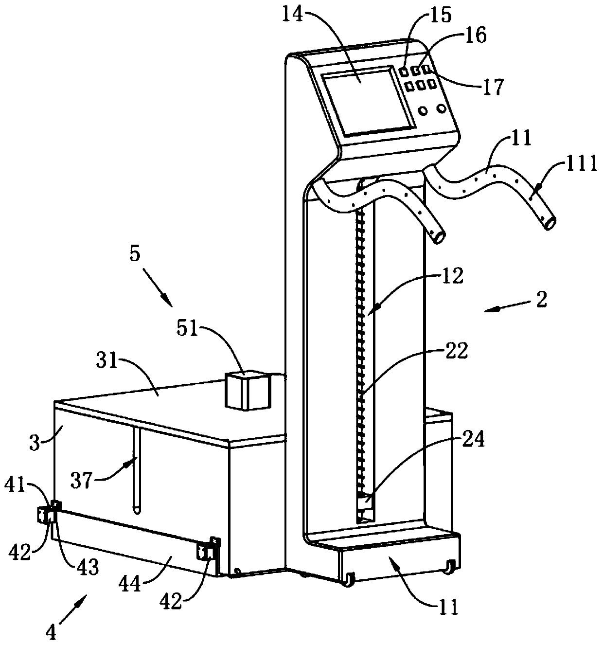
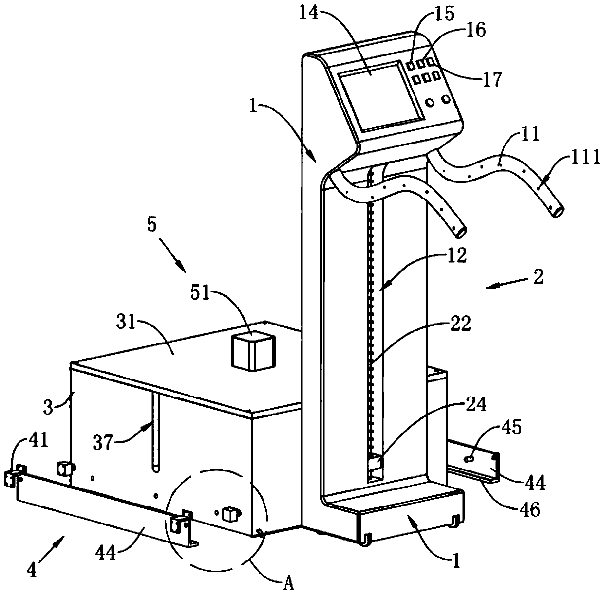
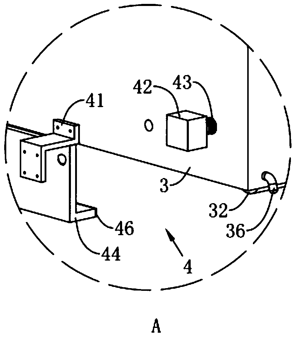
[0032] Reference figure 1 with figure 2 The multifunctional tile laying device shown includes a vertical cart 1, which is arranged in a similar "L" shape, and the push end of the vertical cart 1 is fixedly connected with two push handles 11, the push handle The surface of 11 is provided with a friction-enhancing anti-skid pattern 111. The vertical cart 1 is equipped with a lifting assembly 2 far away from its pushing end. The lifting assembly 2 is raised and lowered in the height direction of the vertical cart 1, and the lifting assembly 2 is detachably connected and placed A number of brick paving cylinders 3 stacked on top of each other. The shape of the paving cylinder 3 and the inner wall of the cylinder are all arranged in a square shape. Two of the opposite sides of the paving cylinder 3 are connected with each other in the paving cylinder 3. Groove 37, the through groove 37 communicates with the opening of the tile tube 3 facing the sealing plate 31, the channel of the t...

Embodiment 2

[0056] The difference between Embodiment 2 and Embodiment 1 is:

[0057] Reference Picture 11 As shown, the pusher 5 includes four guide rods 53 fixedly connected to the end surface of the sealing plate 31 away from the tile cylinder 3, the guide rods 53 and the sealing plate 31 are arranged in parallel to each other, and the end of the guide rod 53 away from the sealing plate 31 is fixedly connected and limited. Position block 531, the four guide rods 53 are plugged into the same second motor 54. The driving end of the second motor 54 rotates coaxially with threads penetrating the sealing plate 31 and facing the first lead screw 55 in the tile drum 3, pushing the plate 52 is rotatably connected to the end of the first screw 55 away from the second motor 54, and two opposite sides of the pressing plate 56 abut the inner wall of the tile drum 3. The vertical cart 1 is provided with a second button 16 for controlling the operation of the second motor 54 of the pushing member 5 on ...


PUM


Abstract

The invention discloses a multifunctional brick paving device. The multifunctional brick paving device is characterized by comprising a vertical cart, wherein the vertical cart is provided with a lifting assembly, the lifting assembly is detachably connected with a brick paving cylinder for placing bricks, a channel of the brick paving cylinder is arranged towards the ground or the wall surface, alimiting assembly for limiting the bricks from falling out or allowing the bricks to slide out is arranged at one end of the brick paving cylinder along the channel, a cylinder opening of one end, far away from the limiting assembly, of the brick paving cylinder is detachably connected with a sealing plate for sealing the cylinder opening of the brick paving cylinder, and the sealing plate is provided with a pushing piece for pushing the bricks in the brick paving cylinder. By adopting the arrangement, the pushing piece is used for pushing the bricks in the brick paving cylinder to enable thebricks to move towards the ground or the wall surface and carry out brick paving, so that most of manual operation is replaced, and the effect of improving the working comfort of people is achieved under the multifunctional action of paving floor bricks and paving wall bricks of the whole structure.

Description

Technical field [0001] The invention relates to the technical field of tile laying tools, in particular to a multifunctional tile laying device. Background technique [0002] Many households usually pave bricks during decoration. The steps of paving bricks are as follows: 1. Clean up the floating slurry and floor ash at the base level; 2. According to the horizontal standard line and the design thickness, pop out the surface on the surrounding walls and columns. The elevation control line of the layer; 3. The position where the bricks are discharged on the bottom plate, and the cross control line and the grid line pop up on the base floor; 4. The base layer is wetted, and a plain cement slurry is brushed on the base layer, while laying and mixing Uniform dry hard cement mortar; 5. Place the bricks on the previously laid mortar by hand and level with a rubber hammer at the same time; 6. Use a ruler to check the flatness of the tiled floor on the upper surface of the pavement; 7. ...

Claims


Application Information

Patent Timeline
IPC IPC(8): E04F21/18E04F21/22
CPCE04F21/18E04F21/1838E04F21/22
Inventor 古敬青
Owner 乐陵市卓亚新型建材有限公司
Why Eureka
Try Eureka