Hot air drying device with safety protection mechanism for cable outer sheath processing

A safety protection and hot air drying technology, which is applied in the directions of heating devices, drying gas arrangement, and drying solid materials, etc., can solve the problems of low production efficiency, low dielectric loss, low dielectric constant, etc., and achieve high adjustability and high applicability , the effect of sticking tightly

Inactive Publication Date: 2020-08-25
嘉兴达宝文线缆有限公司
View PDF5 Cites 2 Cited by
  • Summary
  • Abstract
  • Description
  • Claims
  • Application Information

AI Technical Summary

Problems solved by technology

[0002] The cable is usually a rope-like cable twisted by several wires or groups of wires. Each group of wires is insulated from each other and is often twisted around a center. The entire outside is covered with a highly insulating covering layer. In the air or installed underground or underwater, used for telecommunications or power transmission, the insulating material used for cables should have high insulation resistance, high breakdown electric field strength, low dielectric loss and low dielectric constant, commonly used in cables The insulation materials used include oil-impregnated paper, polyvinyl chloride, polyethylene, cross-linked polyethylene, rubber, etc., and the cable sheath needs to be installed on the outside of the cable as a whole with equipment to achieve the effect of prot

Method used


Image

  • Hot air drying device with safety protection mechanism for cable outer sheath processing
  • Hot air drying device with safety protection mechanism for cable outer sheath processing
  • Hot air drying device with safety protection mechanism for cable outer sheath processing

Examples


Example Embodiment

[0025] The technical solutions in the embodiments of the present invention will be clearly and completely described below with reference to the accompanying drawings in the embodiments of the present invention. Obviously, the described embodiments are only a part of the embodiments of the present invention, but not all of the embodiments. Based on the embodiments of the present invention, all other embodiments obtained by those of ordinary skill in the art without creative efforts shall fall within the protection scope of the present invention.

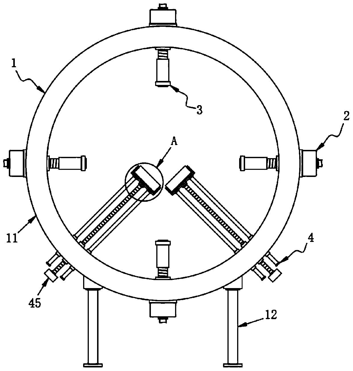
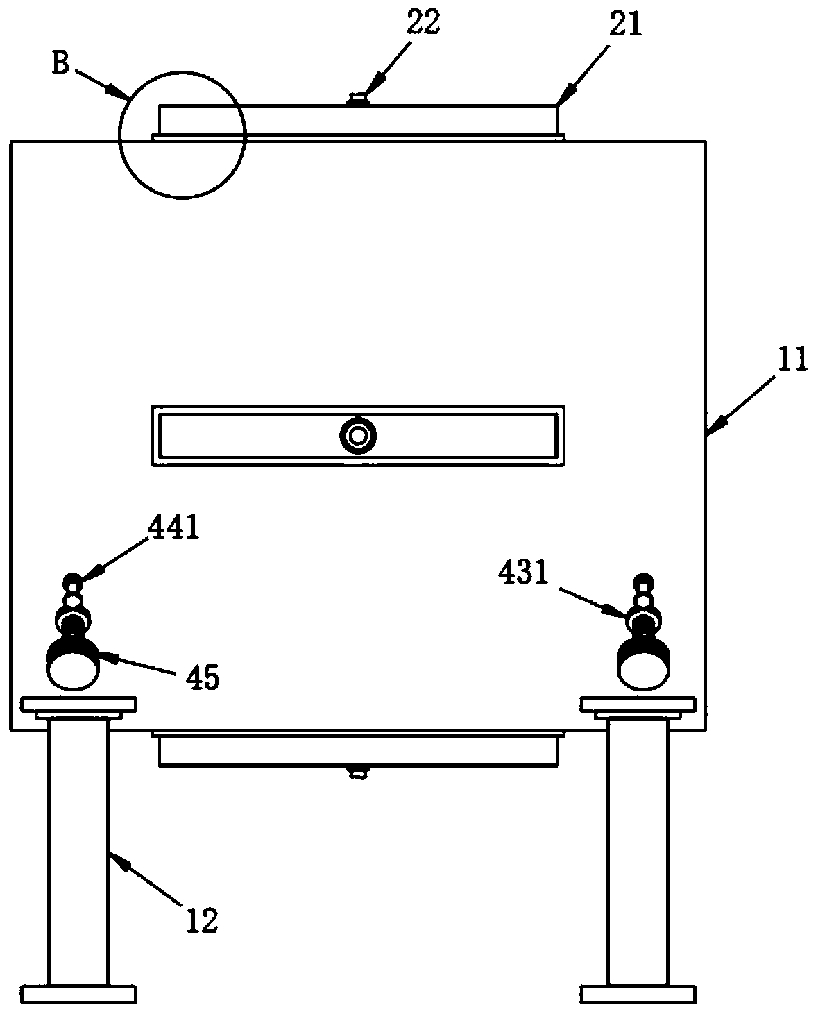
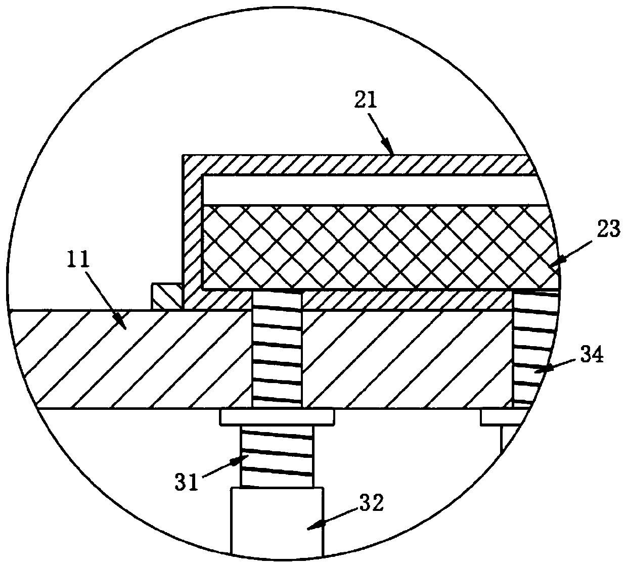
[0026] see Figure 1-5 , the present invention provides the following technical solutions: a hot air drying device for processing a cable outer sheath with a safety protection mechanism, including a support mechanism 1, a heating mechanism 2 and a conveying mechanism 3, the support mechanism 1 includes an installation pipe 11 and a leg 12, and the installation Both ends of the bottom surface of the pipe 11 are fixedly connected with t...


PUM


Abstract

The invention belongs to the technical field of cable sheath processing equipment, and particularly relates to a hot air drying device with a safety protection mechanism for cable outer sheath processing. The hot air drying device with the safety protection mechanism for cable outer sheath processing comprises a supporting mechanism, a heating mechanism and a conveying mechanism. The supporting mechanism comprises a mounting pipe and supporting legs, and two ends of the bottom surface of the mounting pipe are fixedly connected with the two symmetrically arranged supporting legs. The four heating mechanisms are arranged on the periphery of the outer wall of the mounting pipe at equal intervals. A cable penetrates through the inner side of the mounting pipe and is located at the center of the mounting pipe, an external air feeder conveys air flow into the heating box, the air flow is heated through an electric heating net, the temperature of the heated air flow is high, and the high-temperature air flow is conveyed to a spray head through a threaded pipe, a threaded conveying pipe and a threaded sleeve pipe and finally sprayed out of the spray head to the outer side wall of a cable sheath to heat and dry the cable sheath, so that the inner side of the cable sheath is better bonded and fixed with the outer wall of a cable, and the attachment is very tight.

Description

technical field [0001] The invention belongs to the technical field of cable sheath processing equipment, and in particular relates to a hot air drying device for processing cable outer sheaths with a safety protection mechanism. Background technique [0002] The cable is usually a rope-like cable twisted by several wires or groups of wires. Each group of wires is insulated from each other and is often twisted around a center. The entire outside is covered with a highly insulating covering layer. In the air or installed underground or underwater, used for telecommunications or power transmission, the insulating material used for cables should have high insulation resistance, high breakdown electric field strength, low dielectric loss and low dielectric constant, commonly used in cables The insulation materials used include oil-impregnated paper, polyvinyl chloride, polyethylene, cross-linked polyethylene, rubber, etc., and the cable sheath needs to be installed on the outsid...

Claims


Application Information

Patent Timeline
IPC IPC(8): F26B13/10F26B21/00F26B23/06F26B25/00
CPCF26B13/108F26B21/004F26B23/06F26B25/003
Inventor 崔跃峰朱云芬陆峰丁娟芬
Owner 嘉兴达宝文线缆有限公司
Why Eureka
Try Eureka