
Double-straight-area bent optical fiber cone and application thereof

An optical fiber, curved technology, applied in the direction of beam optical fiber, optics, optical components, etc., can solve the problems of unsatisfactory radiation resistance, reduce glass light transmittance, radiation damage, etc., to reduce mutual crosstalk, The effect of reducing crosstalk of light and improving transmittance

Active Publication Date: 2020-08-25
CHINA BUILDING MATERIALS ACAD
View PDF22 Cites 1 Cited by
  • Summary
  • Abstract
  • Description
  • Claims
  • Application Information

AI Technical Summary

Problems solved by technology

However, this method will also bring negative effects. First, the use of cerium oxide will reduce the light transmittance of the glass itself
Second, its radiation resistance effect is still not ideal, and there will still be a large number of high-energy rays penetrating components to reach the back-end semiconductor devices, causing radiation damage

Method used


Image

  • Double-straight-area bent optical fiber cone and application thereof
  • Double-straight-area bent optical fiber cone and application thereof
  • Double-straight-area bent optical fiber cone and application thereof

Examples


Embodiment 1

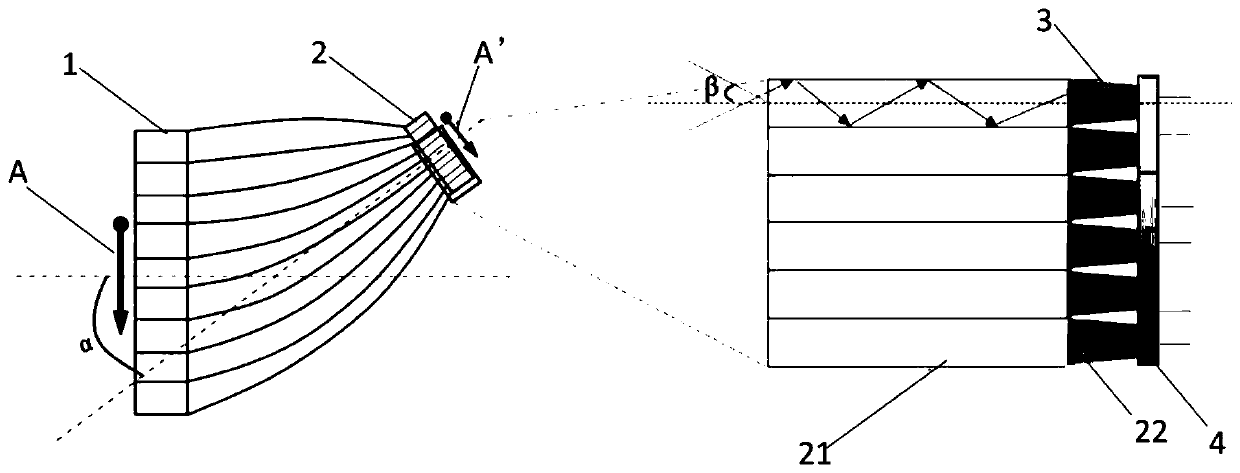
[0058] This embodiment proposes a "horn" type optical fiber for particle detection.

[0059] When the optical fiber taper is working, when the high-energy particle beam input from its large end passes through the front-end element, part of it is absorbed, or scattered, or converted into carriers or photons in the front end, and part of it will penetrate the element Enter the detection elements such as CCD or CMOS at the back end. The "horn" optical fiber cone at the middle end transmits light and image while the design of bending shape can prevent the high-energy particle beam from directly irradiating the detection element, thereby improving the radiation resistance of the device. The material, structure and performance of this "horn" type optical fiber cone are detailed as follows:

[0060] The materials are as follows:

[0061] The core material and skin material of the optical fiber cone are made of glass material with high expansion coefficient, and the expansion coeffi...

Embodiment 2

[0083] This embodiment proposes a "horn" optical fiber cone for low-light night vision imaging.

[0084] The optical fiber cone for low-light night vision imaging is mainly used as the anode of the device, that is, the window of the image output end, which mainly plays the role of light transmission and image transmission. At the same time, the image is enlarged and reduced in equal proportions, which can be used according to actual imaging. Either the big end or the small end can be placed in the vacuum chamber as the input if required. The image is imaged at the output of the fiber optic cone and can be viewed directly or through an eyepiece.

[0085] The "ox horn" optical fiber taper of this embodiment is set so that the end faces of the core layer at the input end and the output end are both slightly convex spherical cap structures, which can significantly improve the light storage capacity of the input end, and at the same time can converge the output light to improve Op...


PUM

PropertyMeasurementUnit
sizeaaaaaaaaaa
diameteraaaaaaaaaa
diameteraaaaaaaaaa

Abstract

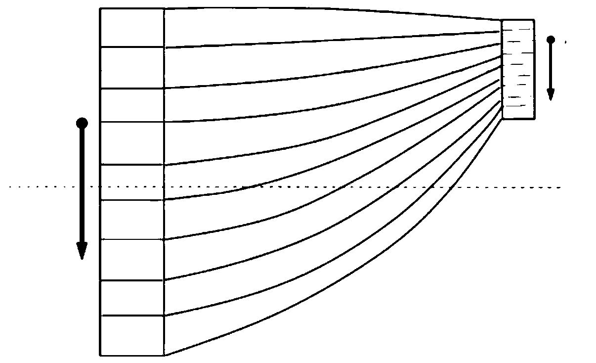
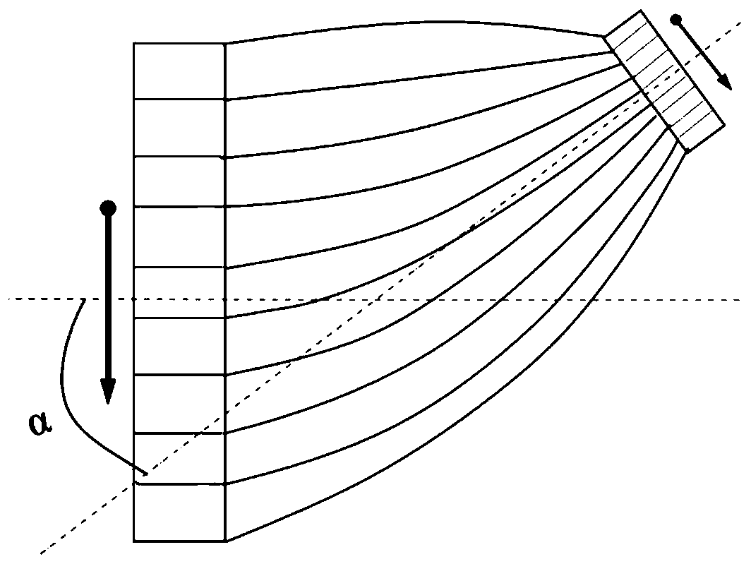
The invention mainly aims to provide a double-straight-area bent optical fiber cone and application thereof. The optical fiber cone comprises a large end and a small end, and the optical fibers forming the large end are arranged in parallel to form a large end straight area; the optical fibers forming the small end are arranged in parallel to form a small end straight area; and the central axis ofthe large-end straight area and the central axis of the small-end straight area are not on the same straight line. The technical problem to be solved is to design a double-straight-area bending shapeand an end face three-dimensional structure. The light rays emitted to the CCD by the light cone are automatically gathered; avoiding divergence, crosstalk of light between the optical fibers is reduced. According to the invention, the coupling efficiency of the light cone and the CCD, the light transmittance and the resolution are improved, the coupling imaging quality is improved, the radiationdamage to a coupling device is reduced, the radiation resistance of the device is improved, and the progress of digital low-light imaging and particle detection technologies is promoted, so that thedevice is more practical.

Description

technical field [0001] The invention belongs to the technical field of optical devices, and in particular relates to a curved optical fiber taper with a special structure and its application. Background technique [0002] Optical fiber cone (hereinafter referred to as light cone) is an optical device made of a large number of optical fibers through regular arrangement, heating, pressure fusion and stretching process; because the light cone has the function of magnifying and reducing the image by a specific factor, and can obtain The object image distance is very small, so it becomes one of the core components of image enhancement devices, and is widely used in miniaturized image equipment and image digitization equipment. [0003] In addition to the above zoom-in and zoom-out imaging, another key function of the light cone is the coupling with the CCD to convert the image into a digital signal through coupling to realize image processing and long-distance transmission. Howe...

Claims


Application Information

Patent Timeline
Patent Type & Authority Applications(China)
IPC IPC(8): G02B6/06G02B6/26
CPCG02B6/06G02B6/262
Inventor 黄永刚付杨周游王云王久旺焦朋蔡京生王叶
Owner CHINA BUILDING MATERIALS ACAD
Learn More