Diode marking machine

A marking machine and diode technology, which is applied in the field of semiconductor processing equipment, can solve the problems of diode pin bending, environmental wind direction rotation, displacement of diode casing, fracture, etc., to reduce the included angle, avoid wear, and reduce damage rate Effect

Inactive Publication Date: 2020-08-25
李秀碧
View PDF0 Cites 0 Cited by
  • Summary
  • Abstract
  • Description
  • Claims
  • Application Information

AI Technical Summary

Problems solved by technology

[0004] The object of the present invention is to provide a diode marking machine to solve the problem of mass production of diodes. The way of placing the marking objects is conveyor belt transportation. According to the structure of the diodes, the existing marking holding devices are tubes with diodes Due to the light weight of the diode shell and its special material, when it is transported to the clamping device, it is easily affected by the wind direction of the environment, and the rotation deviation cannot ensure that each diode shell can be aligned with the clamping device accurately, resulting in The technical problem that the diode pin is bent or even broken by the clamping device

Method used


Image

  • Diode marking machine
  • Diode marking machine
  • Diode marking machine

Examples


Embodiment 1

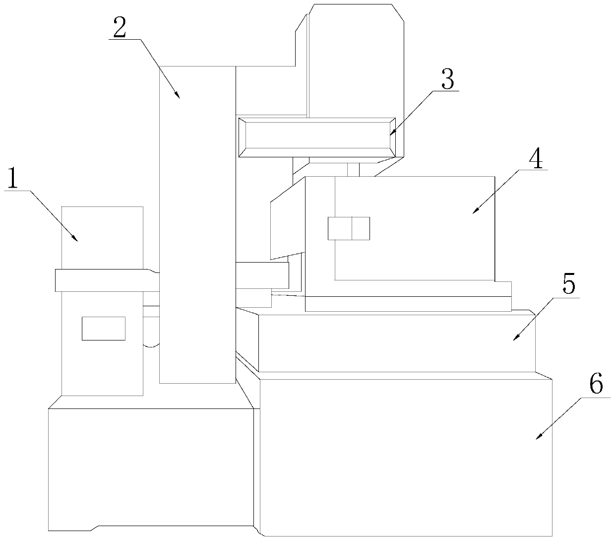
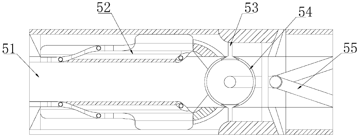
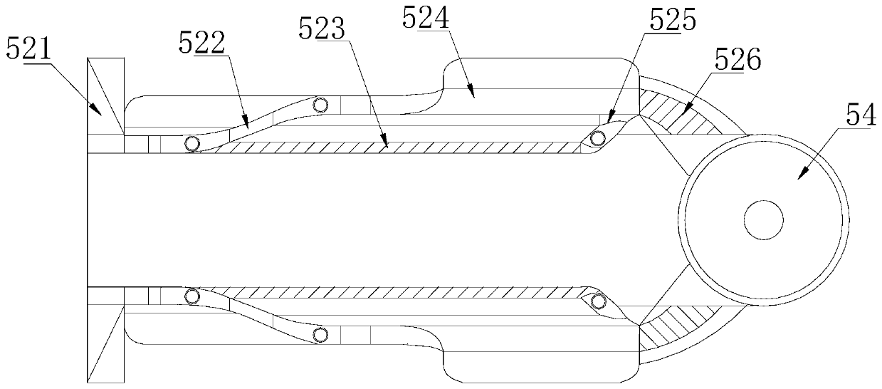
[0033] Such as Figure 1-Figure 6 As shown, the present invention provides a diode marking machine, the structure of which includes a chassis 1, a support 2, a marking head 3, a shield 4, a marking seat 5, and a workbench 6, and the workbench 6 is connected to the chassis 1, Support 2 is installed on the described workbench 6, and this support 2 supports and is fixed on marking head 3 and guard cover 4, and the bottom of described guard cover 4 is fixed on the mark seat 5, and described mark seat 5 and workbench 6. Mechanical connection is adopted. The marking base 5 includes a feeding path 51, a guide mechanism 52, a clamping tube 53, a fixed jaw 54, and a support rod 55. The two sides of the feeding path 51 are respectively provided with a guiding mechanism 52. , the clamping tube 53 fits on the fixed jaw 54 , the fixed jaw 54 is connected and fixed in the feeding channel 51 through the support rod 55 , and the guide mechanism 52 is in clearance fit with the fixed jaw 54 . ...

Embodiment 2

[0040] Such as Figure 7-Figure 8 As shown, on the basis of Embodiment 1, through the mutual cooperation of the following structural components, the buckle 23f includes a ring piece 3f1, a return spring 3f2, a connecting plate 3f3, an inner clip angle 3f4, and a counterweight swivel 3f5. The ring piece 3f1 is arranged inside the connection plate 3f3, the ring piece 3f1 and the return spring 3f2 are semicircular structures, the ring piece 3f1 is in contact with the two ends of the return spring 3f2, and the inner wall of the connection plate 3f3 is equipped with an inner The clamping angle 3f4, the counterweight rotating body 3f5 and the ring piece 3f1 are connected by magnetic adsorption.

[0041] The inner clip angle 3f4 on the right side is in conflict with the ring piece 3f1, the inner clip angle 3f4 on the left side is distributed on both sides of the ring piece 3f1, and does not interfere with each other, and the inner clip angle 3f4 that is in conflict on one side contro...


PUM


Abstract

The invention discloses a diode marking machine which structurally comprises a case, a support, a marking head, a protective cover, a marking base and a workbench. The workbench is connected to the case, the support is installed on the workbench, the support is supported and fixed on the marking head and the protective cover; the bottom of the protective cover is fixed on the marking base; the marking base is mechanically connected with the workbench; the marking base comprises a workpiece feeding channel, a guide mechanism, a clamping pipe, a fixed clamping opening and a supporting rod. A first swing rod, a swing piece and a second swing rod are matched to form a movable rectangular structure, the swing piece is used for limiting the radial area of a workpiece in the horizontal conveyingprocess during workpiece feeding, the situation that deviation is generated due to the influence of the environment wind direction when the workpiece is fed into the fixed clamping opening is avoided,and the damage rate of the workpiece clamped by the fixed clamping opening is reduced.

Description

technical field [0001] The invention relates to the technical field of semiconductor processing equipment, in particular to a diode marking machine. Background technique [0002] A diode is an electronic device made of semiconductor materials (silicon, selenium, germanium, etc.), which has unidirectional conductivity, that is, when a forward voltage is applied to the anode and cathode of the diode, the diode conducts, and when the anode and cathode When the reverse voltage is applied, the diode is cut off. Therefore, the on and off of the diode is equivalent to the on and off of the switch. Diodes are used in various electronic circuits, using diodes and resistors, capacitors, inductors and other components for reasonable connection to form circuits with different functions, which can realize rectification of alternating current, detection of modulated signals, amplitude limiting and clamping, and power supply Diodes with multiple functions such as voltage stabilization are...

Claims


Application Information

Patent Timeline
Patent Type & Authority Applications(China)
IPC IPC(8): H01L21/67H01L21/68B08B17/02
CPCB08B17/02H01L21/67282H01L21/68
Inventor 李秀碧
Owner 李秀碧
Why Eureka
Try Eureka